Z1 COM Z2
Z1 COM Z2
1
2
3
4
NC
NC
NC
NC
NC
NC
Z1 COM Z2
NC Zone 1
TAMPER
TAMPER
Zone 1
Zone 5 (Solution 2000)
Zone 9 (Solution 3000)
(3K3 EOL) (6K8 EOL)
1K0
1K0
Zone 5 (Solution 2000)
Zone 9 (Solution 3000)
(6K8 EOL)
Zone 1
(3K3 EOL)
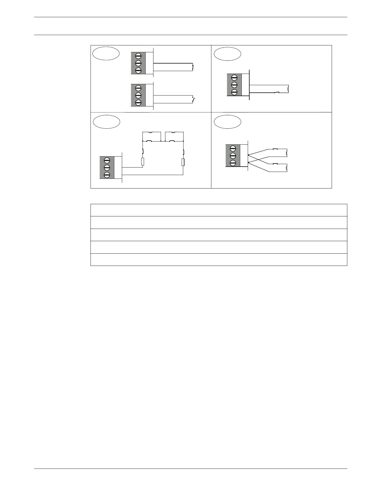
Callout - Description
1 – Zone without resistor (Location 266 = 0 (No EOL), Location 266 = 12 (Normal open))
2 – Single Zone input (Location 266 = 1k, 1k5, 2k2, 3k3, 3k9, 4k7, 5k6, 6k8, 10k, 12k, 22k)
3 – Double Zone with tamper (Location 266 = 14 (Split EOL3K3 / 6K8 with tamper))
4 – Double Zone input (Location 266 = 15 (Split EOL 3k3 / 6k8))
Zone Programming
The programming information for each zone is stored in six locations divided into three
groups. The first three locations determine how the zone operates, the next two locations set
up a number of zone options, and the last location stores the communicator reporting
information for the zone.
Zone Operating Information
These locations store the Zone Type (for example, Delay-1, Instant, or 24-Hour), the Zone
Pulse Count, and the Zone Pulse Count Time. The Zone Pulse Count specifies the number of
times the zone must activate within the time specified in the Zone Pulse Count Time. Refer to
Zone Types, page 97, Zone Pulse Count, page 99, and Zone Pulse Count Time, page 100 for
more information.
Zone Options
These two locations allow you to select from a number of options. Refer to Zone Options 1,
page 100 and Zone Options 2, page 101 for more information.
Zone Reporting Information
This information includes the locations for the Zone Report Options.
The Zone Report Options location enables you to specify how a zone reports to a base station
receiver. Refer to Zone Report Options, page 102 for more information.
Zone Defaults
You can program Zones 1 to 16 as any zone type.
13.3
13.3.1
Control Panel Zone Information | en 93
Bosch Security Systems, Inc. Installation Guide 2017.10 | 03 | F.01U.298.026