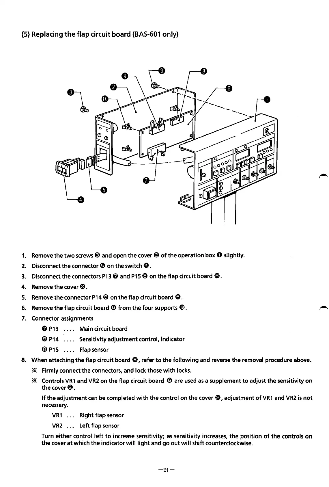
(5) Replacing
the
flap
circuit board
(BAS-601
only)
1.
Remove
the
two
screws@ and open
the
cover@
of
the
operation box 0 slightly.
2.
Disconnect
the
connector @ on
the
switch
e.
3.
Disconnect
the
connectors
P13
fi
and
P15@)
on
the
flap
circuit board
~.
4. Remove
the
cover@.
5.
Remove the·connector
P14@)
on
the
flap
circuit board
@.
6.
Remove
the
flap
circuit board @
from
the
four
supports
CID.
7.
Connector assignments
Main circuit board
8
P13
@)
P14
@)
P15
Sensitivity adjustment control, indicator
Flap sensor
8. When attaching
the
flap circuit board @, refer
to
the
following
and reverse
the
removal procedure above.
* Firmly connect
the
connectors, and lock those
with
locks.
* Controls
VR1
and
VR2
on
the
flap
circuit board
@are
used
as
a supplement
to
adjust
the
sensitivity on
the
cover@.
If
the
adjustment can be completed
with
the
control on
the
cover@,
adjustment
of
VR1
and
VR2
is
not
necessary.
VR
1 . . . Right
flap
sensor
VR2
. . . Left flap sensor
Turn
either
control
left
to
increase sensitivity;
as
sensitivity increases,
the
position
of
the
controls
on
the
cover
at
which
the
indicator
will
light
and
go
out
will
shift
counterclockwise.
-91-
From the library of: Superior Sewing Machine & Supply LLC
 Loading...