~
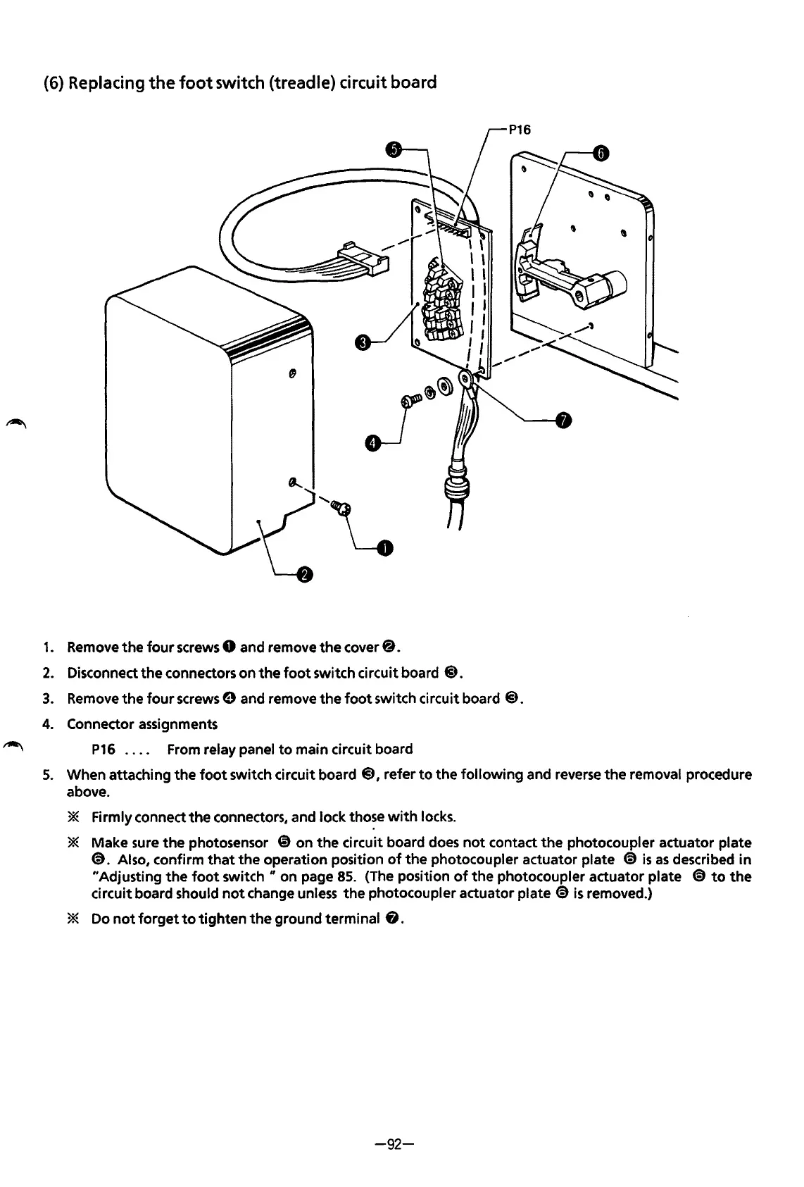
(6) Replacing
the
foot
switch (treadle) circuit board
1.
2.
3.
4.
5.
Remove
the
four
screws 0 and remove
the
cover@.
Disconnect
the
connectors on
the
foot
switch circuit board
@).
Remove the
four
screws e and remove
the
foot
switch circuit board
@).
Connector assignments
P16
. . . . From relay panel
to
main circuit board
When attaching
the
foot
switch circuit board
@),
refer
to
the
following
and reverse
the
removal procedure
above.
* Firmly connect
the
connectors, and lock those
with
locks.
* Make sure
the
photosensor
@on
the
circuit board does
not
contact
the
photocoupler actuator plate
@.
Also, confirm
that
the operation position
of
the
photocoupler actuator plate @
is
as
described
in
"Adjusting
the
foot
switch"
on page
85.
(The position
of
the
photocoupler actuator plate
€)
to
the
circuit board should
not
change unless
the
photocoupler actuator plate
€)
is
removed.)
* Do
not
forget
to
tighten
the
ground terminal
8.
-92-
From the library of: Superior Sewing Machine & Supply LLC
 Loading...