6-37 Confidential
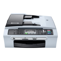
For wireless LAN-enabled models, remove the front cover and WLAN PCB using the
following steps.
(4) Release the grounding wire by removing the screw.
(5) Disconnect the WLAN PCB harness from the main PCB.
(6) Lightly pull up the retainer on the inside of the front cover to release it from the lower cover.
Then lightly lift up the front end of the lower cover and remove the front cover together with
the WLAN PCB.
(7) Release the two latches on the front cover and take out the WLAN PCB.
(6_32_e)
Main PCB
Lower cover
Retainer
WLAN PCB harness
Grounding wire
Front cover
Screw, pan (s/p washer)
M3x8
Latch
Latch
WLAN PCB
WLAN PCB
harness
Grounding wire
Linear boss
Linear boss
Assembling Notes
• For wireless LAN-enabled models: When mounting the front cover and WLAN PCB onto the
lower cover, route the WLAN PCB harness and grounding wire as shown above.
• When mounting the front cover, lightly lift up the front end of the lower cover and fit the linear
boss provided on the inside bottom of the front cover on the bottom of the lower cover.
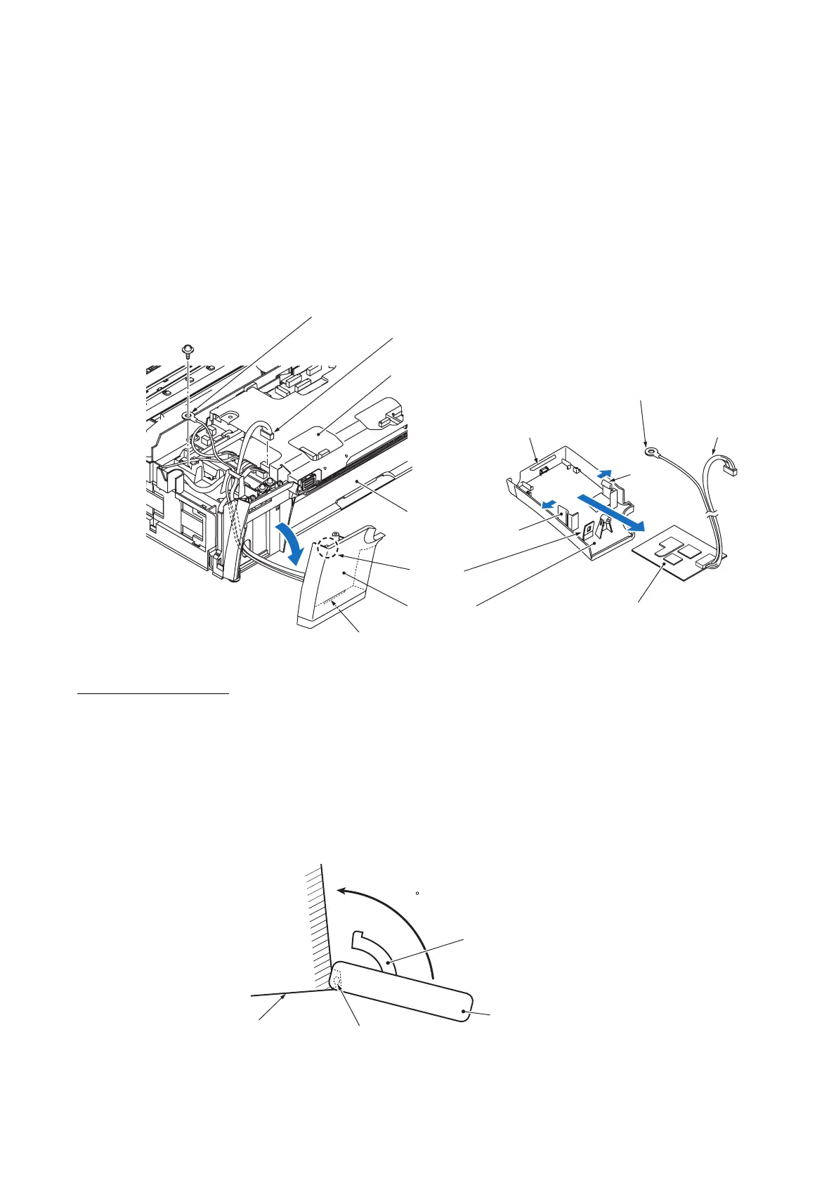
• When mounting the ink cartridge cover, lightly lift up the frond end of the lower cover, fit the
two sockets over the bosses on the lower cover at the angle shown below and rotate the ink
cartridge cover. Then, set the cover arm on the rib on the right side of the lower cover (see the
illustration on the previous page).
(Ink_cartridge_cover)
Cover arm
Ink cartridge cover
Lower cover
Fit the sockets provided on the ink
cartridge cover over the bosses on
the lower cover.
110
 Loading...