3-22 Confidential
3.2.2.2 Head maintenance mechanism
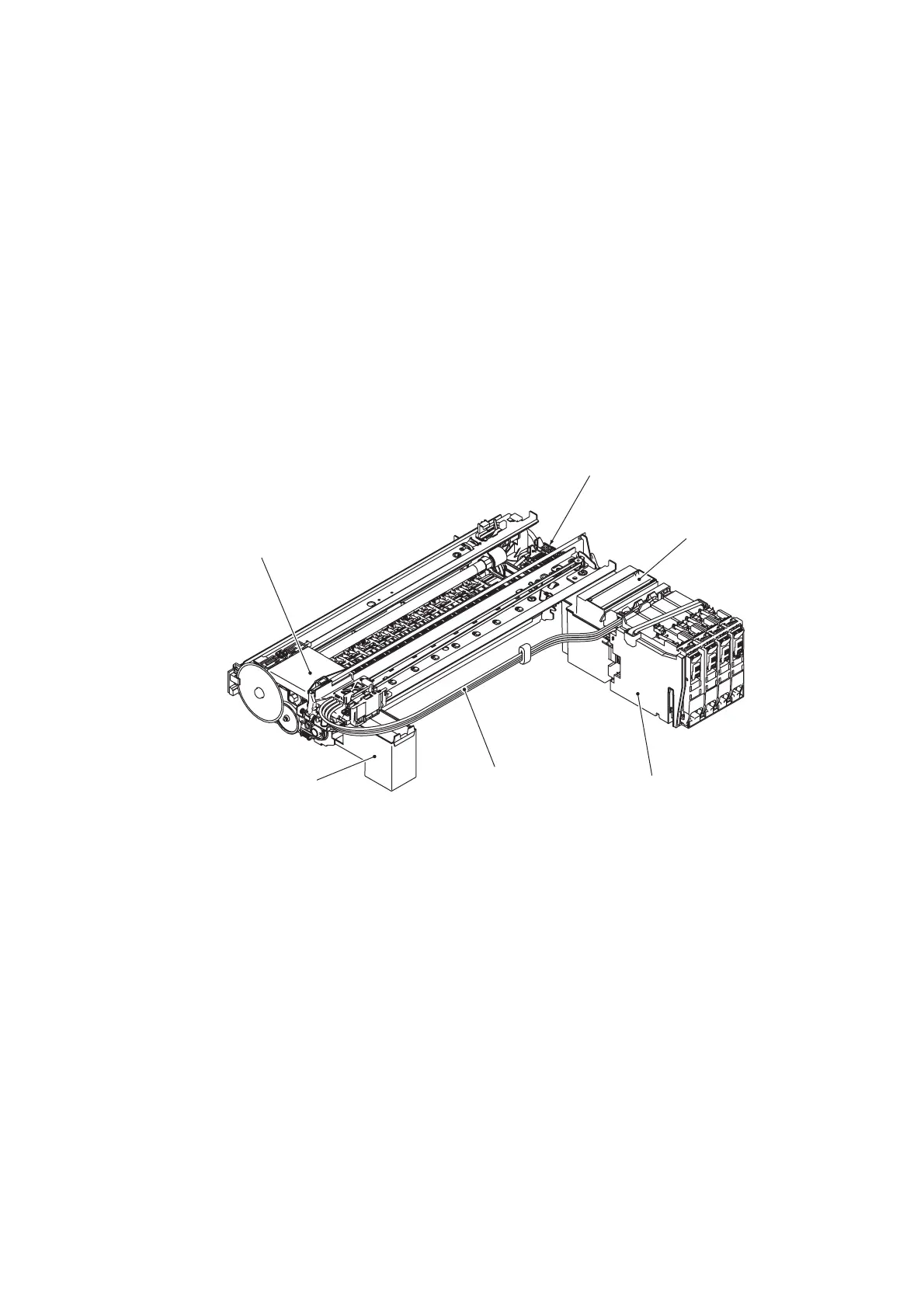
[ 1 ] Overview
The head maintenance mechanism consists of the maintenance unit and the ink absorber box. (See
the illustration below.)
The maintenance unit has the following mechanisms.
- Head capping mechanism (See page 3-24.)
- Carriage lock mechanism (See page 3-25.)
- Purge mechanism (See page 3-25.)
- Head wiper mechanism (See page 3-27.)
- Air removing mechanism (See page 3-28.)
The ink absorber box absorbs the ink sucked out by purge operations.
(3_05)
(Head/carriage unit)
Flushing box
(Ink supply tubes)
(Ink refill assembly)
Ink absorber box
Maintenance unit
[ 2 ] Maintenance unit components
See the illustration given on the next page.
- Pump switching unit
This switches the application target of the negative pressure generated by the tube pump (see the
next page) between the head cap for black ink, the one for color ink, and the air vent cap. Usually
the pump switching unit is switched to the opening tube to the atmospheric air so that the
pressure in the head caps and air vent cap is equal to the normal atmospheric pressure.
- Purge cam
This rotating cam drives the carriage lock, the pump switching unit, the air vent rods, the head
wiper, etc.
- Head/carriage lock
This locks the head/carriage unit in its home position so that the head cap unit (see the next page)
protects the head nozzles.