II - 1
CHAPTER II THEORY OF OPERATION
2.1 OUTLINE OF MECHANISMS
2.1.1 Print Mechanism
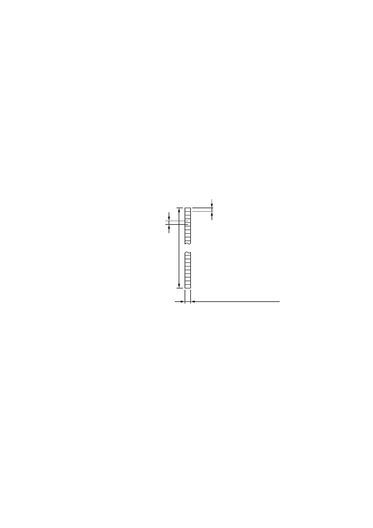
■ Structure of Thermal Head
This machine adopts direct thermal printing system. The thermal head consists of 448
pieces (TD-2020/2120N) or 672 pieces (TD-2130N) of heating elements arrayed in
vertical single row as shown in the Figure 2.1-1.
The dimension of each heating element is vertical length 0.11 (TD-2020/2120N) or 0.07
(TD-2130N) (0.125mm pitch (TD-2020/2120N) or 0.0847mm pitch (TD-2130N)) x
horizontal width 0.132mm (TD-2020/2120N) or 0.11mm (TD-2130N).
Figure 2.1-1 Heating Elements of Thermal Head
■ Printing Process
A thermal paper is pressed against the thermal head in the printing process by the
force comes from a nip between the cylindrical rubber platen and the thermal head.
At this timing, voltage is applied selectively to 448 or 672 pieces of heating elements
arrayed on the thermal head. By this voltage application, the heating elements
generate heat and the thermal tape develops dots by itself at heat sensing points.
After application of voltage the thermal paper is fed to the next printing position by the
platen (0.0847 or 0.125mm).
This printing cycle is repeated and characters and geometries are printed on the tape.
One time travel distance (0.0847 or 0.125mm) is shorter than the width of a heating
element (0.11 or 0.132mm), so that continuous printing cycle can print characters and
geometries on a tape by developing dots with no gap.
Length
TD-2020/2120N: 0.11mm
TD-2130N: 0.07mm
Pitch
TD-2020/2120N: 0.125mm
TD-2130N: 0.0847mm
TD-2020/2120N: 0.132mm
TD-2130N: 0.11mm

 Loading...