Home
Bruker
Measuring Instruments
M4 TORNADO
Bruker M4 TORNADO User Manual
5
of 1
of 1 rating
165 pages
Give review
Manual
Specs
To Next Page
To Next Page
To Previous Page
To Previous Page
Loading...
Using the M4 TORNADO Software
132
User Manual
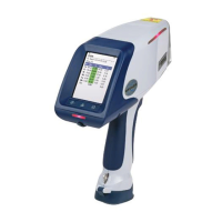
Fig. 63
Taking a
white standard
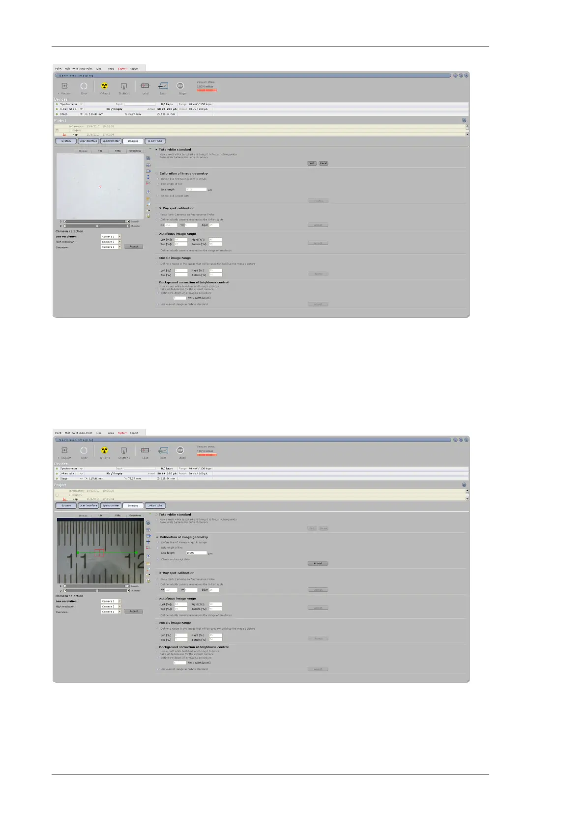
6.12.4
Adjustment of the image size
The image size for both low and high m
agnification can be set in the workspace
System>>Imaging
. These
settings are stable and do not need re
peated adjustments.
Fig. 64
Adjustment of image size
131
133
Table of Contents
Default Chapter
3
Table of Contents
3
1 Introduction
11
About this Manual
11
User Information
11
Intended Usage
12
Warranty and Liability
12
2 Safety Instructions
13
General Information
13
Basic Safety Requirements
13
Safety Instructions for Handling Beryllium
14
Safety Requirements for the Place of Installation
14
Radiation Protection
14
Protection against Electric Current
15
Protection against Mechanical Movements
16
Staff Requirements
16
Safety Equipment
16
Table 1 Safety Equipment of the M4 TORNADO
17
Warning Labels and Name Plates
18
Fig. 1 Safety Equipment on the Front Panel of the M4 TORNADO
18
Table 2 Warning Labels and Name Plates of the Electronic Units
18
3 Functional Principles
19
X-Ray Fluorescence
19
Fig. 2 Emergence of X-Ray Fluorescence Radiation
19
Detection of X-Ray Quanta
20
Digitalization and Channel Allocation
20
Fig. 3 Emergence of a Digital X-Ray Spectrum
21
Spectroscopic Resolution
22
Fig. 4 Definition of FWHM
22
Composition of a Spectrum
23
Evaluation of X-Ray Fluorescence Spectra
23
Fig. 5 Typical Composition of an XRF Spectrum
23
Table 3 Steps of Spectrum Evaluation
24
4 The M4 TORNADO System
27
Product Description
27
Product Features
27
Product Versions
27
Hardware System Components
28
Fig. 6 Components of the M4 TORNADO System
28
Table 4 Connections of the M4 TORNADO System Components
28
Spectrometer
29
Instrument Control PC
30
Table 5 Technical Parameters of the M4 TORNADO
30
Technical Parameters
30
Vacuum System
30
Hardware Installation
32
Room Planning
32
Electrical Connection
33
Fig. 7 Room Planning for the Installation of the M4 TORNADO
33
Table 6 Electrical Connections
33
External Requirements
34
Table 7 External Requirements
34
5 The M4 TORNADO Software
35
Program Description
35
Start-Up and Login
35
Main Menu
35
Fig. 8 Structure of the M4 TORNADO Software
36
Main Screen Areas
37
Display and Control Elements
37
Analysis Options
39
Fig. 9 Example of an Import/Export Menu
39
Volumes, Files and Folders
40
Software Installation
40
Installation of the Program
40
Table 8 Steps for Program Installation
41
Installation of the USB Camera Driver
42
Connection of PC and Instrument
43
Table 9 Steps for USB Camera Driver Installation
43
Table 10 Generation of Connection between Instrument and Instrument PC (Windows ® XP)
44
Table 11 Generation of Connection between Instrument and Instrument PC (Windows ® 7)
45
Installation of a New Software Version
46
Table 12 Definition of the Ehternet Address
46
Table 13 Installation of a New Software Version
46
Registration
47
User Administration
47
The Communication Server
47
Assigning New Users
47
Altering User Name and Password
48
Deleting Users
48
Establishing the Operating State
48
General Operating Instructions
48
Fig. 10 QUANTAX Communication Server
48
Starting the Operation
50
Table 14 Steps for the Instrument Start
50
Running the Program Without Measurement
51
Running the Program Without Instrument
51
Finishing the Operation
51
Fig. 11 Switching off the Instrument
52
6 Using the M4 TORNADO Software
53
Getting Started
53
Fig. 12 Start-Up Screen of the Program M4 TORNADO
53
Table 15 Functions and Settings of the Start-Up Screen
53
Main Program Window and Settings
54
Fig. 13 Main Program Window of M4 TORNADO
54
Table 16 Functions for Display Control
54
Hardware Area
56
Table 17 Icons of the Hardware Area
56
Device Area
57
Fig. 14 Device Area
57
Fig. 15 Spectrometer Line and Spectrometer Settings Dialog
57
Fig. 16 Tube Line and Tube Settings Dialog
58
Fig. 17 Stage Line
59
Table 18 Options for Tube Settings
59
Table 19 Options for Stage Settings
60
Fig. 18 Project Area
61
Project Area
61
Table 20 Options in the Project Area
61
Acquiring Spectra
64
Spectrum Acquisition
64
Fig. 19 Setting the Refresh Time of the Spectrum Image
64
Spectrum Display and Manipulation
65
Fig. 20 Settings for Spectrum Acquisition
65
Fig. 21 Spectra Workspace with Spectrum Display
66
Table 21 Options for Spectrum Display
67
Spectra Matching
70
Fig. 22 Spectrum Matching
70
Table 22 Steps for the Spectra Matching Procedure
71
Qualitative and Quantitative Analysis
72
Element Identification
72
Table 23 Interactive Peak Identification
72
Table 24 Automatic Peak Identification
74
Quantitative Analysis with M4 TORNADO
75
Fig. 23 Spectrum Display with Quantification Results
75
Standardless Analysis for Bulk Materials
76
Fig. 24 Selection of a Quantification Method
76
Table 25 Options for the Selection and Definition of a Quantification Method
76
Fig. 25 Method Editor
77
Table 26 Options for the Definition of Element Properties for Quantification
77
Fig. 26 Result Presentation for Interactive Quantification
80
Table 27 Result Presentation for Interactive Quantification
81
Table 28 Quantification Results Display
82
Fig. 27 Results Tab
83
Fig. 28 Parameter Tab
83
Fig. 29 Spectrum Tab
84
Table 29 Energy Calibration of the Current Spectrum
84
Standard-Based Analysis for Bulk Materials
85
Quantitative Analysis of Coating Systems (Layer Thickness)
85
Point Analysis
85
Fig. 30 the Point Workspace
85
Definition of Measurement Conditions
86
Table 30 Options for the Sample Image
86
Table 31 Options for Mosaic Imaging
88
Measurement and Data Evaluation
89
Quantification
89
Multi-Point Analysis
89
Fig. 31 Definition of Acquisition Parameters
89
Fig. 32 Point Analysis - Result
89
Definition of Measurement Conditions
90
Fig. 33 the Multi-Point Workspace
90
Table 32 Functions of the Multi-Point Workspace
90
Measurement and Data Evaluation
92
Quantification
92
Fig. 34 Definition of Acquisition Parameters
92
Fig. 35 the Multi-Point Workspace - Result
92
Auto-Point Analysis
93
Definition of Measurement Conditions
93
Fig. 36 the Auto-Point Workspace
93
Table 33 Functions of the Auto-Point Workspace
93
Measurement and Data Evaluation
96
Fig. 37 Definition of Acquisition Parameters
96
Quantification
97
Fig. 38 Spectrum Field for Auto-Point Measurement
97
Fig. 39 Spectrum Selection in the *.Spl Format
97
Line Scan Analysis
98
Definition of Measurement Conditions
98
Fig. 40 the Line Workspace
98
Table 34 Functions of the Line Workspace
98
Fig. 41 Settings for Line Scan Acquisition
99
Measurement and Data Evaluation
100
Fig. 42 Profiles Display on the Line Workspace
100
Table 35 Options for Data Evaluation in the Line Workspace
100
Quantification of Line Distributions
101
Area Analysis - Mapping
102
Definition of Measurement Conditions
102
Fig. 43 the Area Workspace
102
Table 36 Options of the Area Workspace
102
Measurement and Data Evaluation
104
Fig. 44 Settings for Area Data Acquisition
104
The Map Result Tab
105
Fig. 45 Map Data on the Area Workspace
105
Fig. 46 Map Result Display on the Area Workspace
105
Table 37 Options for the Map Result Display in the Area Workspace
106
Fig. 47 Display of Mapping Information
107
Fig. 48 Definition of Objects on a Map
107
Fig. 49 Map Paint Tool
108
Fig. 50 Map Display Options
108
Table 38 False Color Display
109
The Spectrum Tab
110
Table 39 Element Chart
110
The Line Scan Tab
111
Fig. 51 the Spectrum Tab
111
Fig. 52 the Line Scan Tab
111
The Phases Tab
112
Fig. 53 the Phases Tab
113
Table 40 Options of the Phases Tab
113
Quantification of Area Distributions
116
Using the M4 TORNADO Report Editor
116
Fig. 54 Workspace Report
117
Handling Objects
118
Table 41 Options for the Handling of Objects in the Report Editor
118
Add Drawings and Text
119
Using Placeholders and Auto Text
120
Using Templates
120
Manoeuvering through Reports
120
Using the Clipboard
121
Loading, Saving and Printing
121
Options
121
System Functions
122
System Assignments
122
Fig. 55 the Panel System
122
Table 42 Functions in the System Panel
122
General Display Settings
123
Fig. 56 the Panel User Interface
123
Table 43 Functions in the User Interface Panel
124
Spectrometer Calibration
125
Fig. 57 the Panel Spectrometer
125
Table 44 Functions in the Spectrometer Panel
126
Table 45 Steps for the Energy Calibration
126
Image Settings
127
Fig. 58 the Panel Imaging
127
Table 46 Functions in the Imaging Panel
127
X-Ray Tube Settings
129
Fig. 59 the Panel X-Ray Tube
129
Adjustment of the Instrument
130
Selection of Camera Ports
130
Fig. 60 Selection of a Calibration File
130
Fig. 61 Selection of the Camera Ports
130
Settings for Stage and Joystick
131
Adjustment of the White Standard
131
Fig. 62 Settings for Stage Speed and Joystick Sensitivity
131
Adjustment of the Image Size
132
Fig. 63 Taking a White Standard
132
Fig. 64 Adjustment of Image Size
132
Settings of Image Parameters
133
Table 47 Settings of Image Parameters
133
Settings for the X-Ray Spot Calibration
134
Settings in the Area for Autofocus Calculation
134
Fig. 65 Adjustment of the X-Ray Spot Position
134
Settings in the Area for Mosaic Image
135
Fig. 66 Setting in the Area for Autofocus
135
Fig. 67 Setting of Reduced Area for Mosaic Image
136
Fig. 68 Background Correction of Brightness Control
136
7 Often Used Analytical Procedures
137
Recommended Measurement Parameters
137
Table 48 Recommended Measurements Parameters
137
Point
138
Fig. 69 Point Analysis
138
Table 49 Steps for Point Analysis
139
Multi-Point
140
Fig. 70 Multi-Point Analysis
140
Table 50 Steps for Multi-Point Analysis
141
Auto-Point
142
Fig. 71 Auto-Point Analysis
142
Table 51 Steps for Auto-Point Analysis
143
Line Scan
144
Fig. 72 Line Scan Analysis
144
Table 52 Steps for Line Distribution Analysis
145
Area Analysis
146
Fig. 73 Area Analysis - Mapping
146
Table 53 Steps for Area Analysis
147
Quantification
148
Quantification of a Single Element Spectrum
148
Table 54 Steps for the Quantification of a Single Point Spectra
148
Quantification of Distribution Measurements
149
Table 55 Steps for the Quantification of Distribution Measurements
150
8 Shutdown
151
Switching off the Instrument
151
Stand-By Operation
151
9 Maintenance of the M4 TORNADO
152
Fuse Replacement
152
Table 56 Fuse Replacement
152
Cleaning of the Turntable
153
10 Transportation
154
11 Disposal
155
A Quantification with M-Quant
156
Table 57 Steps for the Calibration with Mquant
156
Table 58 Calculation of Correction Factors
158
B Standard Extent of Delivery for the M4 TORNADO
159
C General Safety Precautions of the M4 TORNADO
160
D Biological Effects of X-Ray Radiation
161
Index
163
5
Based on 1 rating
Ask a question
Give review
Questions and Answers:
Need help?
Do you have a question about the Bruker M4 TORNADO and is the answer not in the manual?
Ask a question
Bruker M4 TORNADO Specifications
General
Brand
Bruker
Model
M4 TORNADO
Category
Measuring Instruments
Language
English
Related product manuals
Bruker minispec mq20
86 pages
Bruker ultraflex Series
44 pages
Bruker ultraflex III
54 pages
Bruker S1 TITAN
67 pages
Bruker VERTEX 70v
20 pages
Bruker CTX
67 pages