HOME
2-38 2002 Buell S3T: Chassis
STEERING HEAD LOCK 2.18
REMOVAL
1. Raise front wheel off floor using FRONT WHEEL SUP-
PORT STAND (Part No. B-41395) and an automotive
engine lift.
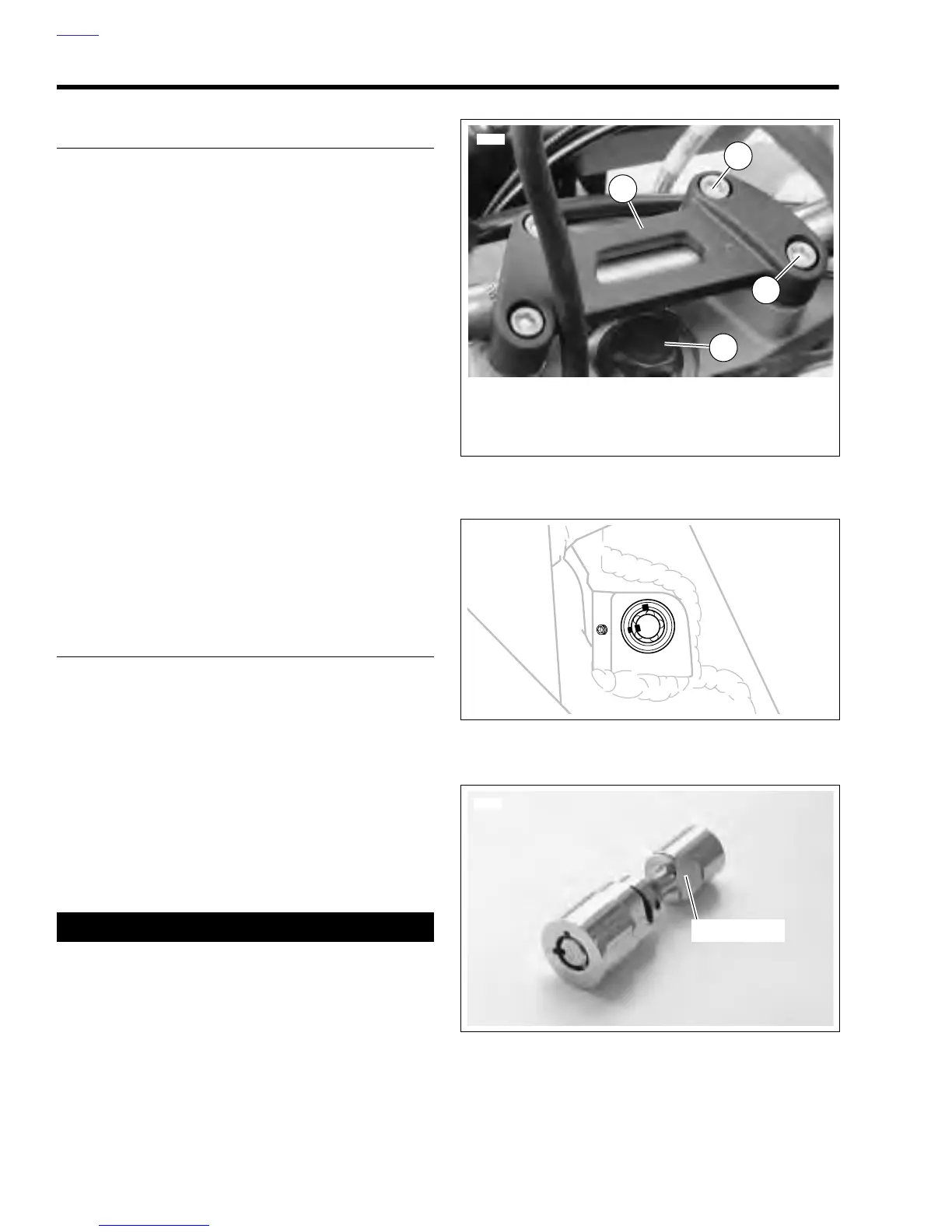
2. See Figure 2-57. Loosen handlebars.
a. Place a protective cover over the fuel tank.
b. Remove both front clamp screws (1).
c. Remove both rear clamp screws (2) and handlebar
clamp (3).
d. Move handlebars to the rear without stretching the
attached cables. Place handlebar assembly on the
protective cover.
3. Loosen the three upper triple clamp screws.
4. Slowly loosen fork stem bolt (4) until forks drop 0.5 in.
(12.7 mm) in triple clamps.
5. See Figure 2-58. Remove set screw behind lock.
6. Extract steering head lock from fork stem.
a. Insert fork key in lock.
b. Lift front wheel upward.
c. Twist key to pull steering head lock from fork stem.
d. Release front wheel.
NOTE
Steering head lock is not repairable. Replace the unit if it fails.
INSTALLATION
1. Install steering head lock in fork stem.
a. See Figure 2-59. Dished area of steering head lock
faces front wheel.
b. Lift front wheel upward.
c. See Figure 2-58. Lock must be in the unlocked posi-
tion to install. Insert lock with key openings posi-
tioned as shown.
d. Release front wheel.
2. See Figure 2-57. Tighten fork stem bolt and triple clamp
screws. Check bearing adjustment. See 2.17 FORK
STEM AND BRACKET ASSEMBLY.
3. Install and adjust handlebars. See 1.20 HANDLEBARS.
11WARNING1WARNING
Operating a vehicle with steering head locked will
restrict the vehicle’s turning ability and may result in an
accident. Always make sure the steering head is not
locked before operating vehicle. Failure to comply could
result in death or serious injury.
4. Install set screw in lock. Test lock.
a. Turn handlebars all the way to the left.
b. Insert ignition key in lock.
c. Turn key clockwise while pushing in.
d. Remove key and verify that steering head is locked.
e. Unlock steering head by inserting key and turning
Figure 2-57. Loosening Handlebars
Figure 2-58. Set Screw
Figure 2-59. Steering Head Lock
6286
1. Front Clamp Screws (2)
2. Rear Clamp Screws (2)
3. Handlebar Clamp
4. Fork Stem Bolt
2
1
3
4
b0442x2x
Dished Area
6310