HOME
2-60 2002 Buell S3T: Chassis
SPROCKET COVER 2.29
REMOVAL/DISASSEMBLY
1. See Figure 2-96. Remove screw on fairing lower.
Remove bracket from stud.
2. See Figure 2-95. Remove two screws from swingarm/
drive support.
3. Remove sprocket cover forward screw, washer and
spacer.
4. Remove swingarm drive/support and sprocket cover as
an assembly.
5. Remove two screws to separate sprocket cover from
swingarm/drive support.
ASSEMBLY/INSTALLATION
1. See Figure 2-95. If removed, attach sprocket cover to
swingarm/drive support.
a. Place sprocket cover behind swingarm/drive sup-
port. Align holes in cover with holes in support.
b. Apply LOCTITE THREADLOCKER 243 (blue) to
both screws.
c. Install screws. Tighten to 12-17 in-lbs (1-2 Nm).
2. Apply LOCTITE THREADLOCKER 243 (blue) to forward
screw. Install sprocket cover assembly with screw,
washer and spacer. Tighten to 48-72 in-lbs (5-9 Nm).
3. Apply LOCTITE THREADLOCKER 272 (red) to two
swingarm/drive support screws and install. Tighten
screws to 20-25 ft-lbs (27-34 Nm).
4. See Figure 2-96. Place fairing lower bracket on stud.
Fasten fairing lower to bracket using screw.
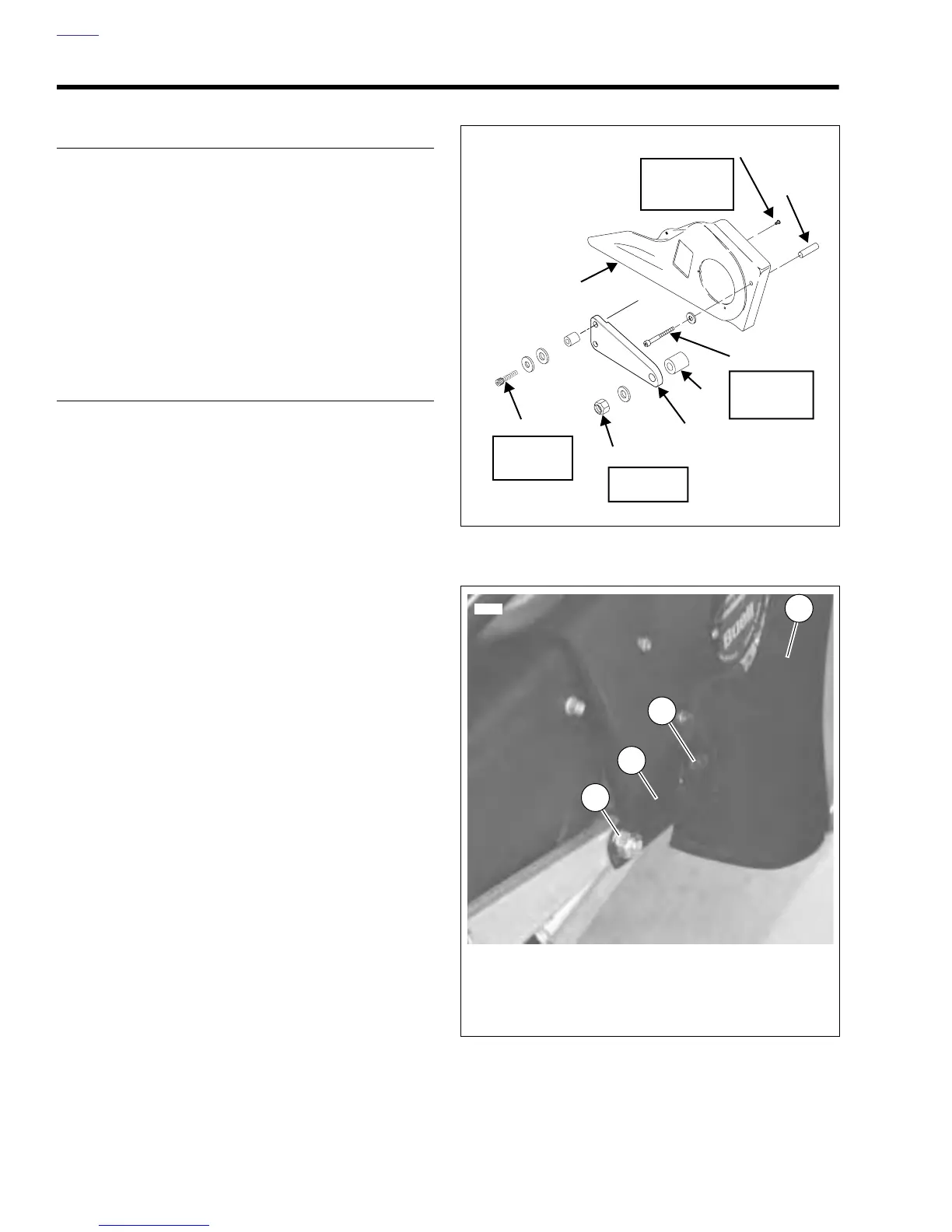
Figure 2-95. Sprocket Cover
Figure 2-96. Fairing Lower Mount
b0204x2a
20-25 ft-lbs
(27-34 Nm)
Screws (2)
Locknut
30-35 ft-lbs
(41-47 Nm)
Swingarm/Drive
Support
Red Loctite
Screw
48-72 in-lbs
(5-9 Nm)
Blue Loctite
Screws (2)
Spacer
Sprocket
Cover
12-17 in-lbs
(1-2 Nm)
Purple Loctite
Spacer
1
8308
3
4
2
1. Nut
2. Bracket
3. Screw and Wellnut
4. Right Fairing Lower