2002 Buell S3T: Fuel System 4-65
HOME
TROUBLE CODES 23 AND 32 4.22
GENERAL
Front Fuel Injector (Code 23)
And Rear Fuel Injector (Code 32)
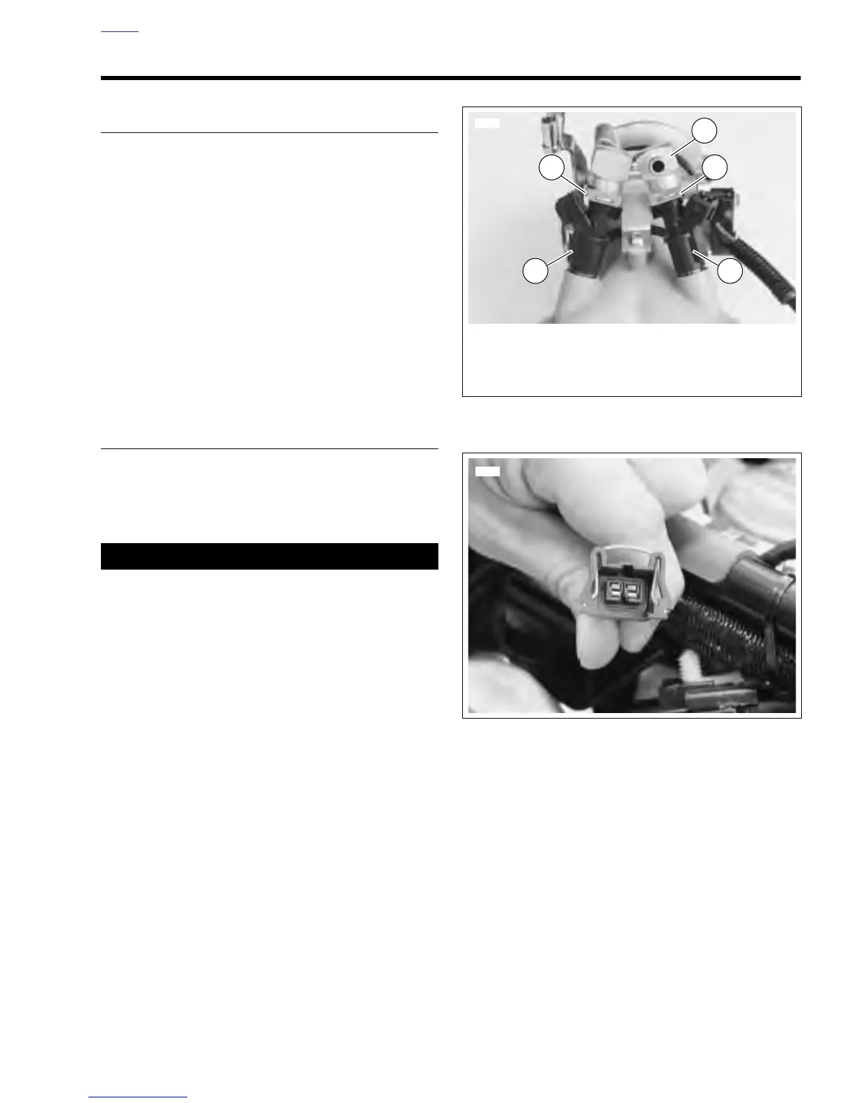
See Figure 4-50. The fuel injectors (1, 2) are solenoids that
allow pressurized fuel into the engine intake tract. The injec-
tors are timed to the engine cycle and are triggered sequen-
tially.
See Figure 4-51. The power for the injectors comes from the
ignition relay. The ignition relay also provides power for fuel
pump, ECM, bank angle sensor and the ignition coils. The
ECM provides the path to ground to trigger the injectors.
NOTE
System fuse and ignition relay failures or wiring harness
problems will cause 12 volt power to be lost to both injectors,
ignition coils, ECM, bank angle sensor and fuel pump.
DIAGNOSTICS
Diagnostic Notes
The reference numbers below correlate with the circled num-
bers on the Code 23/32 flow charts.
11WARNING1WARNING
The gasoline in the fuel supply line downstream of the
fuel pump is under high pressure (49 psi [338 kPa]). To
avoid an uncontrolled discharge or spray of gasoline,
always purge the system of high pressure gas before
removing fuel tank. Gasoline is extremely flammable and
highly explosive. Inadequate safety precautions could
result in death or serious injury.
1. Purge fuel line and remove fuel tank. See 4.36 FUEL
TANK.
2. Use HARNESS CONNECTOR TEST KIT (Part No. HD-
41404), purple pin probes and patch cord.
3. Connect BREAKOUT BOX (Part No. HD-42682) to ECM.
See 4.7 BREAKOUT BOX.
4. Use HARNESS CONNECTOR TEST KIT, purple pin
probes and patch cord to BREAKOUT BOX and gray
socket probes and patch cord to FUEL INJECTOR TEST
LAMP (Part No. HD-34730-2C).
Scanalyzer Notes
The Scanalyzer icon appears at those points in the flow chart
where the Scanalyzer can be used. If a number is printed
next to the icon, then refer to the Scanalyzer notes at the bot-
tom of the flow chart.
Figure 4-50. Fuel Injectors
Figure 4-51. Fuel Injector Connector
6765
1. Front Fuel Injector
2. Rear Fuel Injector
3. Clip (2)
4. Fuel Rail
2
3
4
1
3