7-40 2002 Buell S3T: Electrical
HOME
HANDLEBAR SWITCHES 7.5
REMOVAL
NOTE
The individual handlebar switches are not repairable.
Replace switch assembly upon switch failure.
Right Side
1. Detach throttle cables.
2. Remove seat.
11WARNING1WARNING
The gasoline in the fuel supply line downstream of the
fuel pump is under high pressure (49 psi [338 kPa]). To
avoid an uncontrolled discharge or spray of gasoline,
always purge the system of high pressure gas before
removing fuel tank. Gasoline is extremely flammable and
highly explosive. Inadequate safety precautions could
result in death or serious injury.
3. Purge fuel line and remove fuel tank. See 4.36 FUEL
TANK.
4. See Figure 7-47. Cut as many cable straps as necessary
to access right handlebar switch connector [22] along
right side frame tube. Detach connector [22] from wiring
harness.
5. Cut as many cable straps as necessary to access brake
switch connector [21] along right side frame tube. Detach
connector [21] from wiring harness.
Left Side
1. Remove three screws (metric) from handlebar switch.
2. Separate switch housings and remove from handlebar.
3. Remove seat.
11WARNING1WARNING
The gasoline in the fuel supply line downstream of the
fuel pump is under high pressure (49 psi [338 kPa]). To
avoid an uncontrolled discharge or spray of gasoline,
always purge the system of high pressure gas before
removing fuel tank. Gasoline is extremely flammable and
highly explosive. Inadequate safety precautions could
result in death or serious injury.
4. Purge fuel line and remove fuel tank. See 4.36 FUEL
TANK.
5. Cut as many cable straps as necessary to access left
handlebar switch connector [24] along right side frame
tube. Detach connector [24] from wiring harness.
6. Cut as many cable straps as necessary to access clutch
switch connector [95] along right side frame tube. Detach
connector [95] from wiring harness.
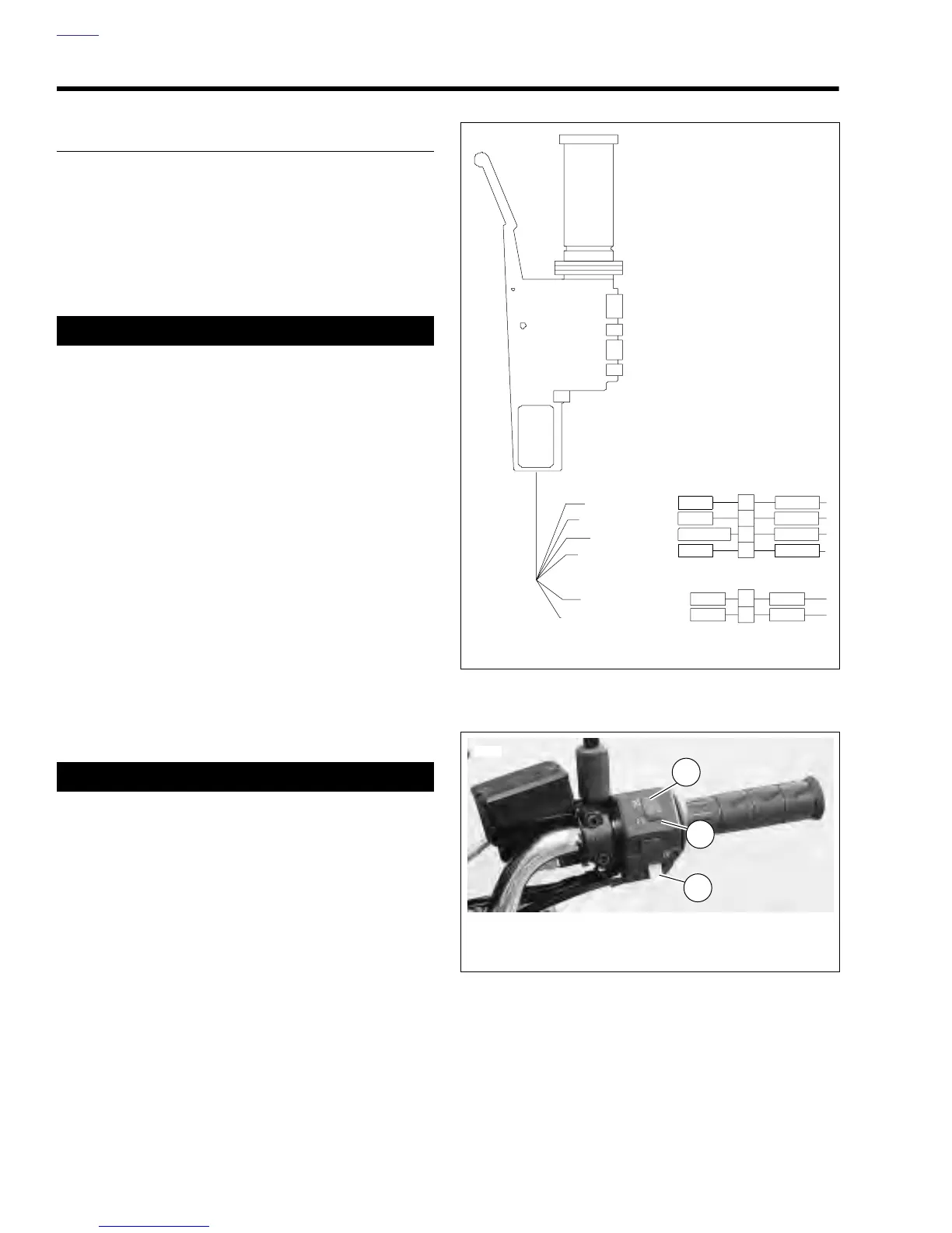
Figure 7-47. Right Handlebar Switch Connection
Figure 7-48. Right Handlebar Switches
IGN MODULE
FROM [2]
GN/BK
W/R W/BK
W/BK
TO STARTER
IGN POWER
TO STOPLIGHT
ACC POWER
1
2
1
3
2
4
O/WO/W
R/YR/Y
Y/R
BE
BK/R
GY/O
b0630x7x
Right Handlebar
Switch [22]
Brake Switch [21]
6925
1. Ignition ON
2. Ignition OFF
3. Electric Starter Switch
1
2
3