2002 Buell S3T: Fuel System 4-7
HOME
SCANALYZER 4.5
SCANALYZER DIAGNOSTICS
Data Link Connector
See Figure 4-6. Using the Scanalyzer requires access to the
data link connector [91A] located in the trunk. Remove the
seat to access the data link connector. See 2.35 SEAT.
Scanalyzer Cartridge
See Figure 4-7. Through a special programmable application
cartridge, the Scanalyzer offers data displays and menu
selections that allow for quick and easy retrieval of data. The
device enables the user to perform a variety of diagnostic
tests while monitoring inputs and outputs.
Sample Scanalyzer menu selections are shown in Figure 4-8.
INSTALLATION
The behavior of the check engine lamp (as described under
CHECK ENGINE LAMP) indicates the presence of trouble
codes. When trouble codes are present, and a SCANA-
LYZER (Part No. HD-41325) and DIAGNOSTIC CARTRIDGE
(Part No. B-41325-99) are available, proceed as follows:
1. Turn ignition/light key switch OFF.
2. See Figure 4-6. Remove the seat. See 2.35 SEAT.
3. Remove rubber protective plug from data link connector.
Plug Scanalyzer into connector. If necessary, detach
connector from frame.
4. Turn ignition/light key switch ON. Set engine stop switch
to RUN, but do not start engine.
5. See Figure 4-7. Insert the diagnostic application car-
tridge (2) into the Scanalyzer (1). During the next few
seconds, the Scanalyzer sequences through a series of
screens that reflect a power-on self test, the system
copyright, and then an attempt at communications with
the ECM. Once communications is established with the
ECM, the diagnostic menu appears. See Figure 4-8.
6. Continue with the instructions under USAGE.
Figure 4-6. Data Link Location
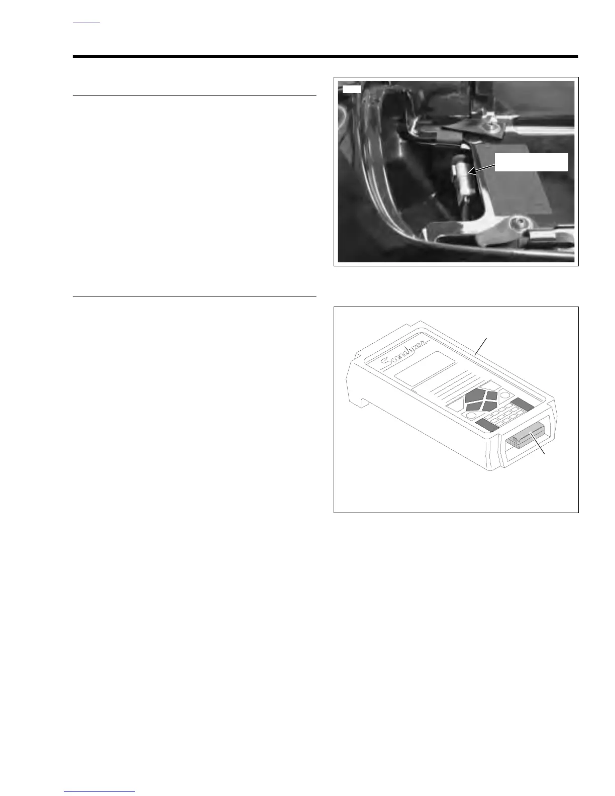
Figure 4-7. Scanalyzer and Cartridge
8304
Data Link
Connector [91A]
1. Scanalyzer (Part No. HD-41325)
2. Cartridge (Part No. B-41325-99)
b0656x4x
1
2