2-18 2002 Buell S3T: Chassis
HOME
FRONT BRAKE MASTER CYLINDER 2.10
REMOVAL
NOTE
Do not remove the master cylinder unless problems are being
experienced.
1. See Figure 2-17. Drain brake fluid into a suitable con-
tainer. Discard of used fluid according to local laws.
a. Open bleeder valve about 1/2-turn.
b. Install a length of plastic tubing over caliper bleeder
valve. Place free end in a suitable container.
c. Pump brake hand lever to drain brake fluid.
d. Tighten bleeder valve to 3-5 ft-lbs (4-7 Nm).
CAUTION
Cover painted surfaces and right handlebar switches and
use care when removing brake reservoir cover and add-
ing D.O.T. 4 brake fluid. Spilling D.O.T. 4 brake fluid on
painted surfaces will result in cosmetic damage. Spilling
brake fluid on switches may render them inoperative.
11WARNING1WARNING
Any leak in the brake system will adversely affect brake
operation. Damaged banjo bolt seating surfaces will leak
when reassembled. Prevent damage to seating surfaces
by carefully removing brake line components. Failure to
comply could result in death or serious injury.
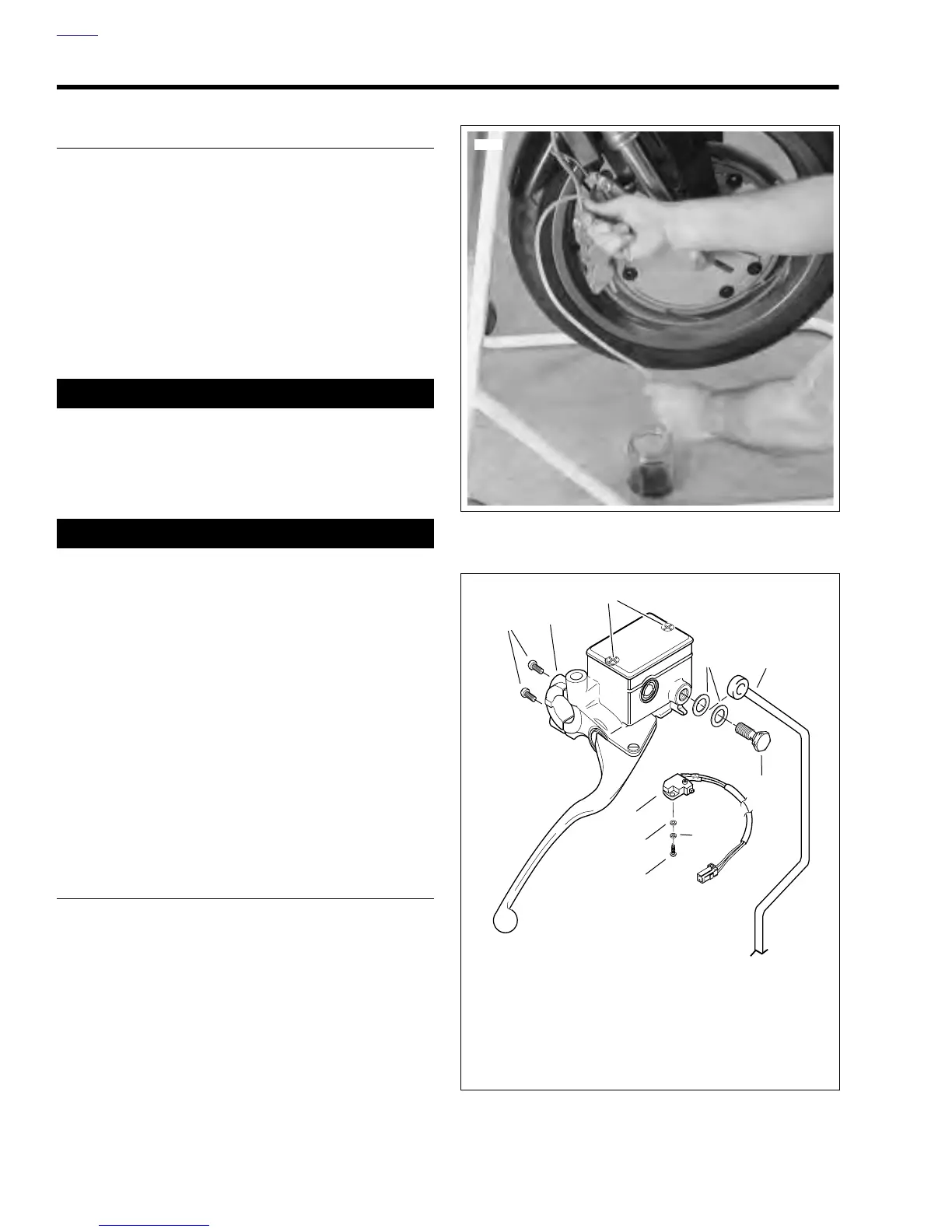
2. See Figure 2-18. Remove banjo bolt (6) (metric) and two
banjo washers (4) to disconnect brake line (5) from mas-
ter cylinder. Discard banjo washers.
3. Remove screw (10), lockwasher (9) and washer (8) to
detach brake lamp switch (7).
NOTE
The individual parts of the brake lamp switch are not service-
able. Replace switch upon failure.
4. Remove two screws (1) (metric) and clamp (2) to detach
master cylinder assembly from handlebar.
DISASSEMBLY
1. See Figure 2-19. Detach front brake hand lever.
a. Remove nut (1) (metric) from lever pivot.
b. Remove pivot bolt (2) from lever pivot.
c. Detach front brake hand lever (3) from master cylin-
der assembly.
2. See Figure 2-20. Remove screw, lockwasher and washer
(1) holding front brake switch (2) to master cylinder
assembly. Remove switch.
3. See Figure 2-21. Compress piston (2) and remove boot
(1).
4. Depress piston assembly and remove internal snap ring
(3). Discard snap ring.
5. See Figure 2-22. Remove piston assembly (1-4) from
front master cylinder.
Figure 2-17. Draining Front Brake System (Typical)
Figure 2-18. Front Master Cylinder
6293
1. Clamp Screws (2)
(metric)
2. Clamp
3. Master Cylinder
Cover Screws (2)
4. Banjo Washers (2)
5. Brake Line
6. Banjo Bolt (metric)
7. Front Brake Lamp
Switch
8. Washer
9. Lockwasher
10. Screw
b0203a2x
1
3
4
2
5
6
7
8
10
9