2002 Buell S3T: Chassis 2-19
HOME
CLEANING AND INSPECTION
11WARNING1WARNING
Clean brake system components using denatured alco-
hol. Do not use mineral-base cleaning solvents, such as
gasoline or paint thinner. Use of mineral-base solvents
causes deterioration of rubber parts that continues after
assembly. This may cause improper brake operation
which could result in death or serious injury.
1. Clean all parts with denatured alcohol or D.O.T. 4
BRAKE FLUID. Do not contaminate with mineral oil or
other solvents. Wipe dry with a clean, lint free cloth. Blow
out drilled passages and bore with a clean air supply. Do
not use a wire or similar instrument to clean drilled pas-
sages in bottom of reservoir.
2. Carefully inspect all parts for wear or damage and
replace as necessary.
3. Inspect piston bore in master cylinder housing for scor-
ing, pitting or corrosion. Replace housing if any of these
conditions are found.
4. See Figure 2-23. Inspect outlet port that mates with
brake line fitting. As a critical sealing surface, replace
housing if any scratches, dents or other damage is
noted.
5. Inspect boot for cuts, tears or general deterioration.
Replace as necessary.
ASSEMBLY
1. See Figure 2-23. Check piston assembly components.
a. Small end of spring (1) sits behind primary cup (2).
Large side of primary cup faces spring.
b. Secondary cup (3) sits within ridge at middle of pis-
ton (4).
2. Insert piston assembly, spring first, into master cylinder.
Secure with a new snap ring (6).
3. Install ridge on boot (5) into groove on piston (4).
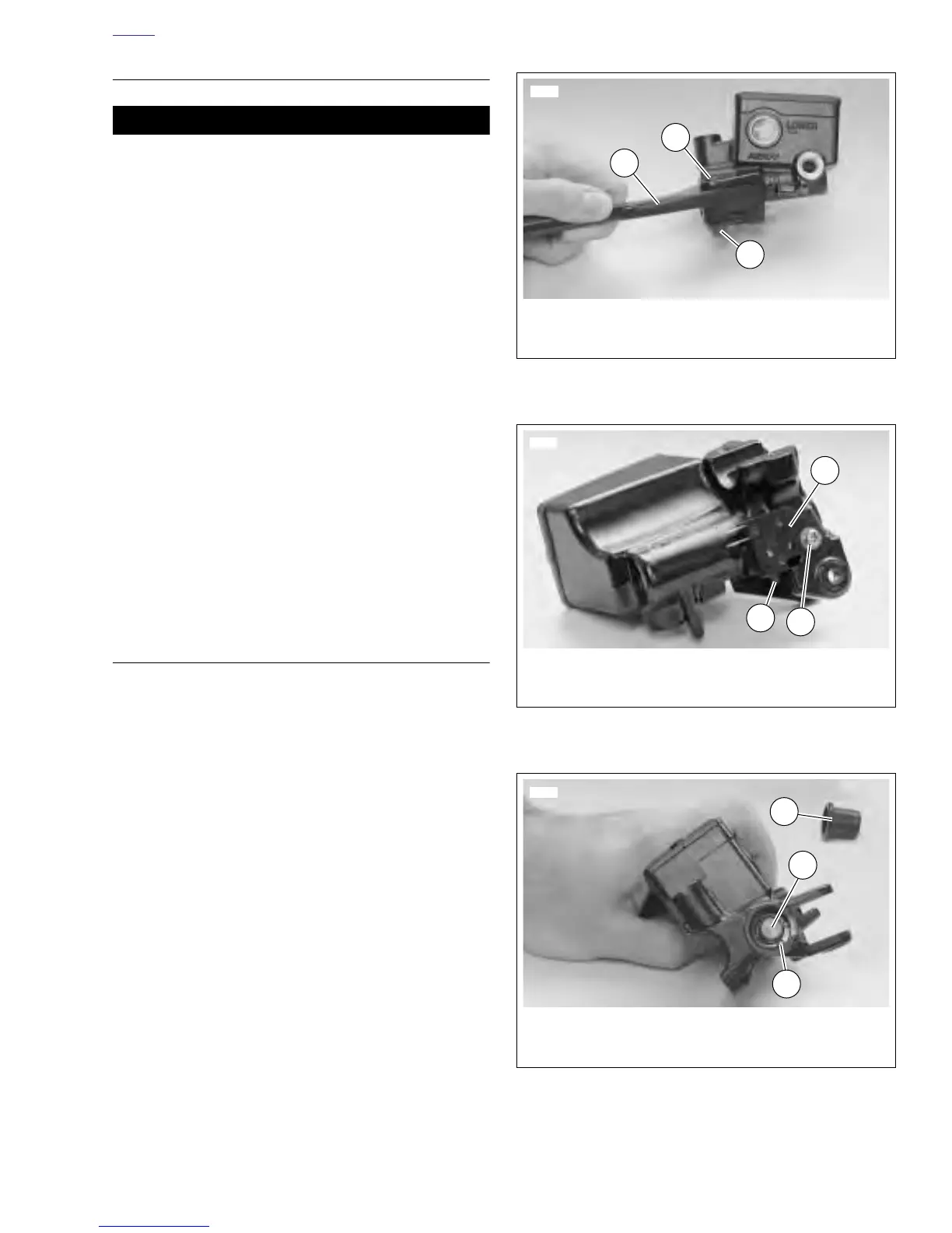
4. See Figure 2-19. Install front brake hand lever.
a. Align hole in lever (3) with hole in master cylinder
assembly.
b. Lubricate pivot bolt (2) with LOCTITE ANTI-SEIZE.
c. Install pivot bolt through top of assembly. Tighten to
4-13 in-lbs (1-2 Nm).
d. Install nut (1) (metric). Tighten to 44-62 in-lbs (5-7
Nm).
5. See Figure 2-24. Install front brake switch.
a. Attach front brake switch with screw, washer and
lockwasher (1). Tighten to 7-13 in-lbs (1-2 Nm).
b. Test switch action. Tang (2) on switch must release
when hand lever (3) is moved.
Figure 2-19. Hand Lever
Figure 2-20. Front Brake Switch
Figure 2-21. Snap Ring
6488
2
3
1
1. Nut (metric)
2. Pivot Bolt
3. Hand Lever
6489
1. Screw, Lockwasher and Washer
2. Front Brake Switch
3. Tang
3
1
2
6490
2
1. Boot
2. Piston
3. Snap Ring
3
1