2-8 2002 Buell S3T: Chassis
HOME
FRONT WHEEL 2.5
REMOVAL
1. Raise front wheel off floor using FRONT WHEEL SUP-
PORT STAND (2) (Part No. B-41395-A) and an automo-
tive engine lift.
2. Detach front brake caliper from rotor. See 2.11 FRONT
BRAKE CALIPER.
NOTE
Do not operate front brake lever with front wheel removed or
caliper pistons may be forced out. Reseating pistons requires
caliper disassembly.
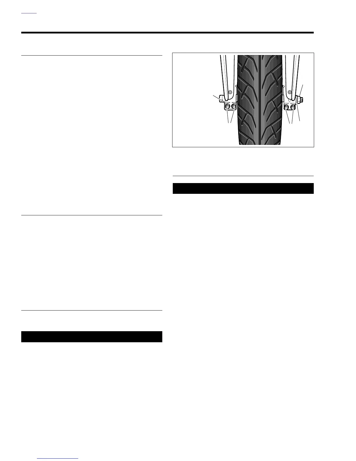
3. See Figure 2-4. Insert screwdriver/rod through hole in
axle (1). Loosen front axle nut (4) (metric).
4. Loosen all four pinch screws (2) (metric).
5. Remove front axle nut (4) and washer (3). Pull front axle
out of wheel hub while supporting front wheel.
6. See Figure 2-5. Remove front wheel.
DISASSEMBLY
1. See Figure 2-5. Move wheel to bench area. On brake
rotor side of wheel, remove right axle spacer (10).
2. Remove wheel bearings (4, 9) using BUSHING AND
BEARING PULLER (Part No. HD-95760-69A) and 3/4 in.
COLLET (Part No. HD-95767-69A).
3. See Figure 2-5. Remove five screws (12) to detach front
brake rotor (15) from wheel hub.
4. Remove tire. See 2.8 TIRES.
CLEANING AND INSPECTION
1. Thoroughly clean all parts in solvent.
1CAUTION
Never use compressed air to “spin-dry” bearings. Very
high bearing speeds can damage unlubricated bearings.
Spinning bearings with compressed air can also cause a
bearing to fly apart, which may result in minor or moder-
ate injury.
2. Inspect all parts for damage or excessive wear.
3. Inspect brake rotor.
a. Measure rotor thickness. Replace if less than ser-
vice wear limit. See 1.7 BRAKE PADS AND
ROTORS.
b. Check rotor surface. Replace if warped or badly
scored.
ASSEMBLY
11WARNING1WARNING
Do not allow brake fluid, bearing grease, lubricants, etc.
to contact brake rotor or reduced braking ability will
occur, which could result in death or serious injury.
1. See Figure 2-5. Install front brake rotor (13) on right side
of wheel. Slots in carrier must line up with wheel spokes.
a. Verify that the front brake carrier is thoroughly clean.
b. Apply LOCTITE THREADLOCKER 243 (blue) to
threads of each of the five T40 TORX screws (12).
c. Install rotor (13) on wheel hub using screws (12).
Tighten screws in criss-cross pattern to 20-22 ft-lbs
(27-30 Nm).
2. See Figure 2-5. Install spacer (8).
3. Install
new
wheel bearings (4, 9) into hub using suitable
driver. Press on outer race only.
4. On the side of the wheel opposite the brake rotor insert
left axle spacer (3) into hub until it seats in bore. Spacer
sleeve must not be cocked or tilted in bore.
5. On the right side of the wheel insert right axle spacer
(10) into hub until it seats in bore. Spacer sleeve must
not be cocked or tilted in bore.
6. Install tire, if removed. See 2.8 TIRES.
7. Verify that wheel and tire are true. See 2.7 CHECKING
CAST RIM RUNOUT.
8. Balance tire. See 2.8 TIRES, Adjustment.
Figure 2-4. Front Wheel Mounting
b0331x2x
1
2
4
2
3
1. Hole in Axle
2. Pinch Screws
(4) (metric)
3. Washer
4. Axle Nut
(metric)