HOME
2-70 2002 Buell S3T: Chassis
SIDE STAND 2.36
GENERAL
11WARNING1WARNING
● If the side stand is not in the full forward position
when vehicle weight is rested on it, the vehicle could
fall over which could result in death or serious
injury.
● Always park motorcycle on a level, firm surface.
Vehicle weight could cause motorcycle to fall over,
which could result in death or serious injury.
The side stand is located on the left side of the motorcycle.
The side stand swings outward to support the motorcycle for
parking.
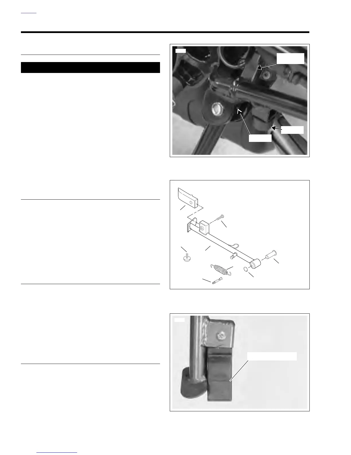
See Figure 2-115. The side stand activates the side stand
switch which is part of the starter interlock system. See 7.6
STARTER INTERLOCK for more information.
REMOVAL/DISASSEMBLY
1. Raise rear wheel off floor using REAR WHEEL SUP-
PORT STAND (Part No. B-41174).
2. See Figure 2-116. Remove spring (6) from side stand
and spring pin (5).
3. Remove retaining clip (7) and pivot pin (8). Detach side
stand from frame.
4. Remove bumper (3) from frame.
5. Remove screw (2) and side stand dragger (1).
INSPECTION
1. Replace dragger when worn to wear line shown in Figure
2-117.
2. Test the side stand in the following manner. Without vehi-
cle weight resting on it, side stand should move freely
into extended (down) and retracted (up) positions.
3. Check sidestand switch (starter interlock) for proper
operation after the first 500 miles and every 2500 miles
thereafter. See 7.6 STARTER INTERLOCK.
ASSEMBLY/INSTALLATION
1. See Figure 2-116. Attach bumper (3) to frame.
2. Attach side stand dragger (1) to side stand with screw
(2).
3. Apply LOCTITE ANTI-SEIZE to pivot pin (8). Install side
stand using pivot pin (8) and retaining clip (7). Do not
crush side stand switch during installation.
4. Connect spring (6) to side stand and spring pin (5).
5. Remove REAR WHEEL STAND.
Figure 2-115. Side Stand Switch
Figure 2-116. Side Stand
Figure 2-117. Side Stand Dragger Wear Limit
Sidestand
Switch
Plunger
8305
Bumper
1
4
3
7
5
6
2
1. Side Stand Dragger
2. Screw
3. Bumper
4. Side Stand
5. Spring Pin
6. Spring
7. Retaining Clip
8. Pivot Pin
8
b0435x2x
Wear Limit Line
6299