2002 Buell S3T: Fuel System 4-89
HOME
CAM POSITION SENSOR AND ROTOR 4.30
GENERAL
See Figure 4-70. The cam position sensor and trigger rotor
are located in the gearcase cover on the right side of the
vehicle. The rotor is mounted on the camshaft and operates
at one-half crankshaft speed. The sensor wiring is connected
to the ignition module wiring harness.
REMOVAL
11WARNING1WARNING
To protect against shock and accidental start-up of vehi-
cle, disconnect the negative battery cable before pro-
ceeding. Inadequate safety precautions could result in
death or serious injury.
1. Disconnect negative battery cable from battery.
2. Remove right fairing lower. See 2.38 FAIRING LOWERS.
3. Remove sprocket cover. See 2.29 SPROCKET COVER.
4. Cut cable straps holding cam position sensor wiring at
the following locations:
a. Starter.
b. Edge of gearcase cover.
c. Oil line.
5. See Figure 4-69. Disconnect cam position sensor wiring
at connector [14] located behind the starter motor.
6. See Figure 4-69. Note position of each cam position sen-
sor wiring terminal in plug end of connector.
7. See Figure 4-70. Remove connector terminal pins. See
Appendix B.
8. Remove timer cover.
a. Drill off heads of outer timer cover pop rivets using a
3/8 in. (9.525 mm) drill bit.
b. Tap remaining rivet shafts inboard through holes in
timer cover and inner cover.
c. Remove timer cover. Remove inner cover screws
and inner cover.
d. Carefully remove any remaining pieces of rivets
from gearcase cover timer bore.
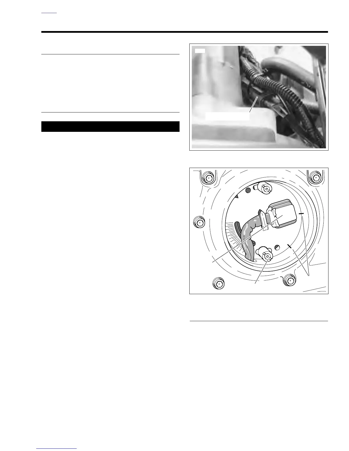
9. See Figure 4-70. To obtain approximate ignition timing
during installation, scribe alignment marks across cam
position sensor in two places.
10. See Figure 4-70. Remove timer plate studs. Carefully
remove cam position sensor. Remove bolt and trigger
rotor.
11. Carefully remove camshaft oil seal if damaged or if there
is any evidence of oil leakage past the seal.
INSTALLATION
1. See Figure 4-69. With the lipped side facing inboard,
install
new
camshaft oil seal into gearcase cover, if
removed. Press seal into position until flush with surface
of timer bore.
2. Install trigger rotor.
a. Apply LOCTITE THREADLOCKER 243 (blue) to
threads of bolt.
b. Position trigger rotor onto end of camshaft aligning
notch with camshaft slot.
c. Install bolt to secure rotor. Tighten to 43-53
in-lbs
(5-6 Nm).
3. Install cam position sensor and timer plate studs. Rotate
cam position sensor to its previously marked position to
obtain approximate ignition timing.
Figure 4-69. Cam Position Sensor Connector [14]
Figure 4-70. Marking Ignition Timing
b0313a7x
Timer Plate Stud
Scribe Marks
Cam
Position
Sensor