5-12 2002 Buell S3T: Electric Starter
HOME
STARTER 5.7
REMOVAL
11WARNING1WARNING
To protect against shock and accidental start-up of vehi-
cle, disconnect the negative battery cable before pro-
ceeding. Inadequate safety precautions could result in
death or serious injury.
11WARNING1WARNING
Always disconnect the negative battery cable first. If the
positive cable should contact ground with the negative
cable installed, the resulting sparks may cause a battery
explosion which could result in death or serious injury.
1. Remove primary cover. See PRIMARY COVER under
6.2 PRIMARY CHAIN.
2. See Figure 5-9. Remove both starter mounting bolts and
washers (1).
NOTE
A ball hex driver may be required to gain access to the starter
mounting bolts.
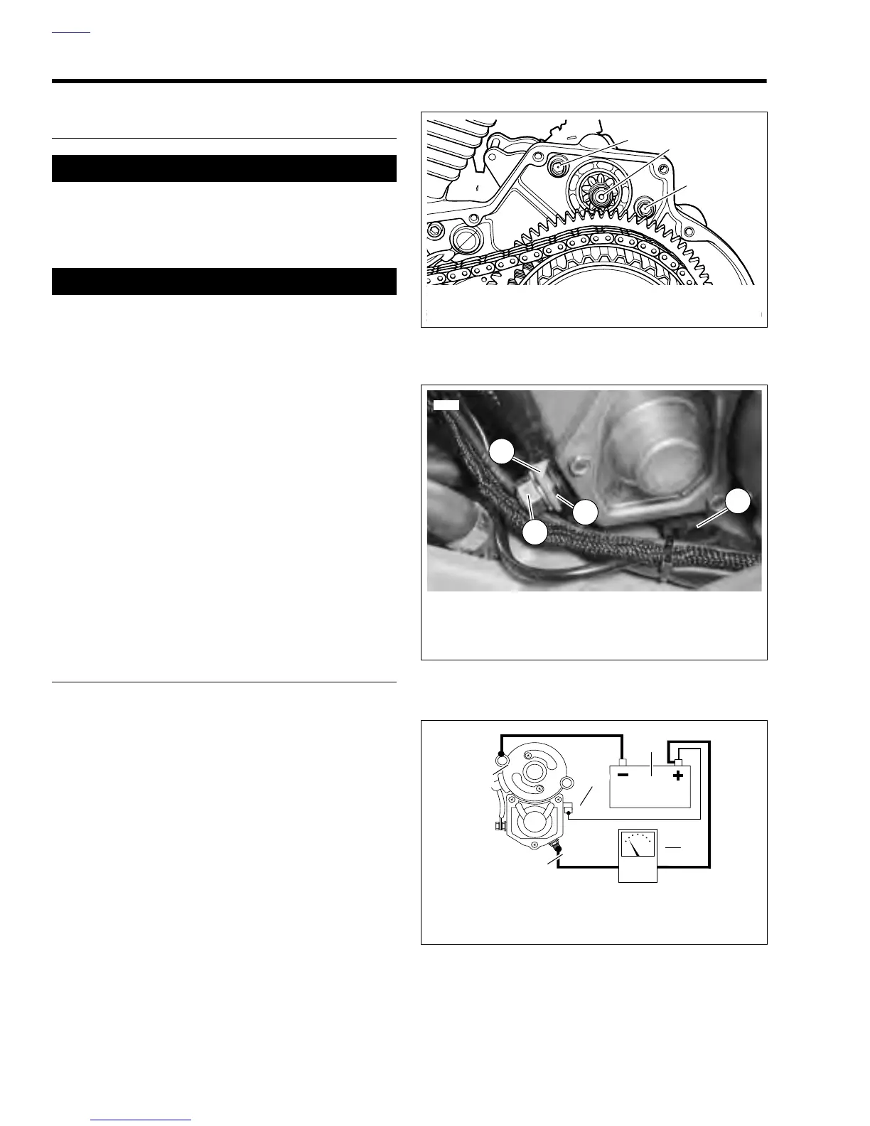
3. See Figure 5-10. Remove nut with washer (1) (metric).
a. Remove positive battery cable ring terminal (2).
b. Remove circuit breaker wire ring terminal (3).
c. Remove protective boot (if equipped) and detach
solenoid wire (4).
4. Remove starter and gasket from the gearcase cover
side.
TESTING ASSEMBLED STARTER
Free Running Current Draw Test
1. Place starter in vise, using a clean shop towel to prevent
scratches or other damage.
2. See Figure 5-11. Attach one heavy jumper cable (6
gauge minimum).
a. To the starter mounting flange (1).
b. To the negative (-) terminal of a fully charged bat-
tery.
3. Connect a second heavy jumper cable (6 gauge mini-
mum).
a. To the positive (+) terminal of the battery (2).
b. To an inductive ammeter (3). Continue on to the bat-
tery terminal (4) on the starter solenoid.
4. Connect a smaller jumper cable (14 gauge minimum).
a. To the positive (+) terminal of the battery (2).
b. To the solenoid relay terminal (5).
5. Check ammeter reading.
a. Ammeter should show 90 amps maximum.
b. If reading is higher, disassemble starter for inspec-
tion. See 5.7 STARTER.
c. If starter current draw on vehicle was over 200 amps
and this test was within specification, there may be a
problem with engine or primary drive.
Figure 5-9. Starter Mounting
Figure 5-10. Starter Wires (Protective Boot Not Shown)
Figure 5-11. Free Running Current Draw Test
1
1
2
b0312x5x
1. Mounting Bolts and Washers
2. Starter
6237
1
1. Nut with Washer (metric)
2. Positive Battery Cable Ring Terminal
3. Circuit Breaker Wire Ring Terminal
4. Solenoid Wire
4
2
3
1. Mounting Flange
2. Battery
3. Induction Ammeter
4. Battery Terminal
5. Relay Terminal
b0439x5x
1
4
3
5
2