3-12 2002 Buell S3T: Engine
HOME
CYLINDER HEAD 3.5
REMOVAL
Before removing the cylinder head assembly, see 3.3 STRIP-
PING MOTORCYCLE FOR ENGINE REPAIR. The rocker
arm covers and internal components must be removed before
removing cylinder heads.
1. See Figure 3-5. Remove screws with washers (1) and
fiber seals (2). Discard fiber seals.
CAUTION
All washers and fasteners used in the engine are hard-
ened. Do not mix or replace hardened washers and fas-
teners with unhardened parts. Do not reuse fiber cover
seals. These actions may result in accelerated wear and
increased noise.
2. Remove upper (4) and middle (5) sections of rocker
cover. Remove and discard gaskets (6, 7 and 8).
3. Rotate crankshaft until piston on head being repaired
reaches top dead center of compression stroke.
NOTE
Both valves in the cylinder head will be closed when viewed
through the spark plug hole.
4. Remove hardware holding lower rocker cover to cylinder
head in the following order.
a. Remove two screws and washers (14).
b. Remove three bolts and washers (15).
c. Remove the two rocker arm retaining bolts (12) near
the push rods.
d. Remove the remaining two rocker arm retaining
bolts (13).
5. Remove lower rocker cover (18).
NOTE
Remove lower rocker boxes as an assembly; then disassem-
ble as required.
6. Mark the location and orientation (top/bottom) of each
push rod. Remove push rods.
CAUTION
Mark rocker arm shafts for reassembly in their original
positions. Valve train components must be reinstalled in
their original positions to prevent accelerated wear and
increased valve train noise.
7. See Figure 3-6. Remove rocker arm shafts by tapping
them out using a hammer and a soft metal punch.
8. See Figure 3-5. Remove rocker arms (10, 11); mark
them for reassembly in their original locations.
CAUTION
Distortion to the head, cylinder and crankcase studs may
result if head screws are not loosened (or tightened)
gradually in the sequence shown in Figure 3-7.
9. See Figure 3-7. Loosen each head screw 1/8-turn follow-
ing the sequence shown.
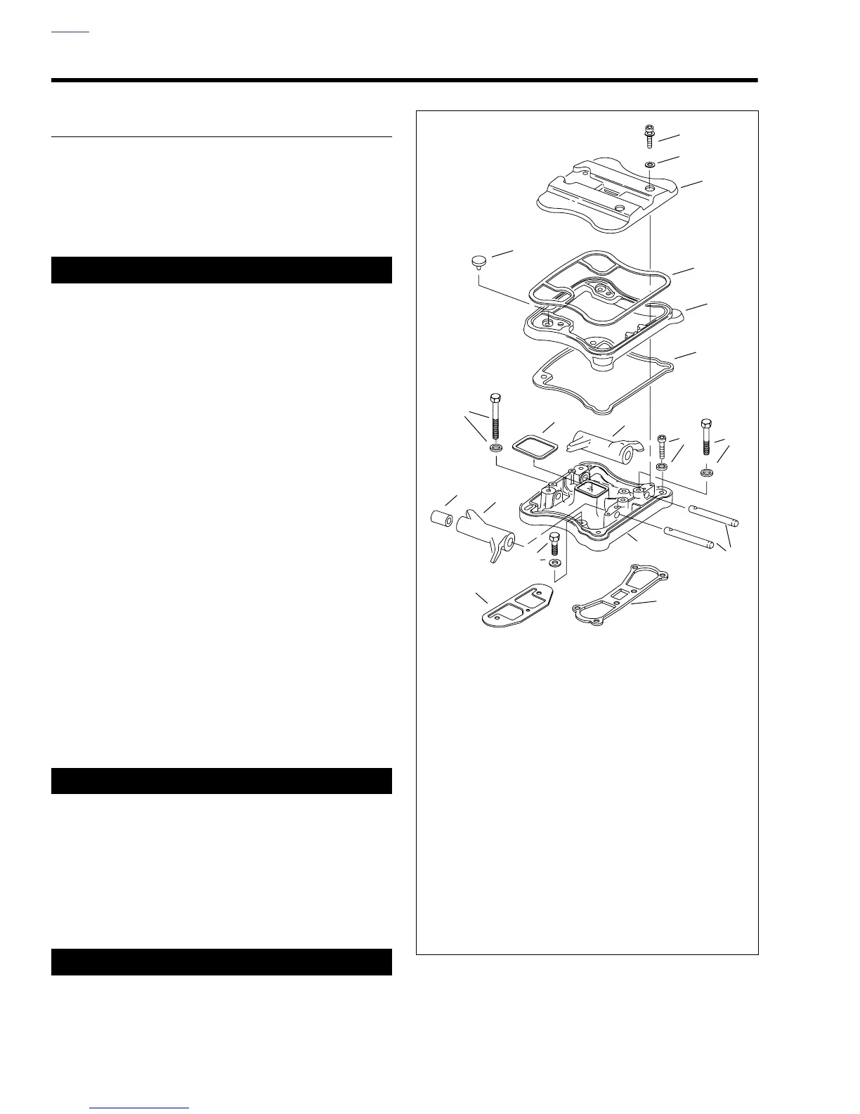
Figure 3-5. Rocker Arm Cover
1. Screws with Washers (4)
2. Fiber Seal (4)
3. Umbrella Valve (2)
4. Upper Rocker Cover
5. Middle Rocker Cover
6. Gasket
7. Gasket
8. Gasket
9. Rocker Arm Shafts
10. Rocker Arm
11. Rocker Arm
12. Bolt and Washer (2) (long)
13. Bolt and Washer (2) (short)
14. Screw and Washer (2)
15. Bolt and Washer (3)
16. Gasket
17. Gasket
18. Lower Rocker Cover
19. Rocker Arm Bushing (8)
b0343x3x
1
2
4
6
5
7
3
13
14
19
11
8
10
16
17
15
18
9
12