2002 Buell S3T: Engine 3-27
HOME
Measuring Piston
Because of their complex shape, the pistons cannot be accu-
rately measured with standard measuring instruments.
The pistons have the typical elliptical shape when viewed
from the top. However, they also are barrel-shaped when
viewed from the side. This barrel shape is not symmetrical.
Any damage to the piston will change its shape, which will
lead to problems.
Fitting Cylinder to Piston
Since pistons cannot be accurately measured with standard
measuring instruments, the bore sizes must be observed.
Bore sizes are listed in Ta ble 3-7. Example: A 0.005 in.
(0.127 mm) oversize piston will have the proper clearance
with a bore size of 3.502 in. ± 0.0002 in. (88.951 mm ±
0.0051 mm) for the 1203cc engine.
Boring and Honing Cylinder
When cylinder requires oversize reboring to beyond 0.030 in.
(0.762 mm), the oversize limit has been exceeded and cylin-
der must be replaced.
1. Bore cylinder with gaskets and torque plates attached.
Bore to 0.003 in. (0.076 mm) under the desired finished
size.
2. Hone the cylinder to its finished size using a 280 grit rigid
hone followed by a 240 grit flexible ball hone. Honing
must be done with the torque plates attached. All honing
must be done from the bottom (crankcase) end of the
cylinder. Work for a 60° crosshatch pattern.
Fitting Piston Rings
NOTE
Ring sets and pistons, 0.040 in. (1.016 mm) oversize, are not
available on 1203cc engines.
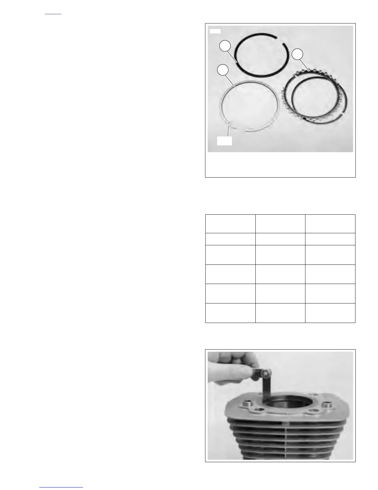
See Figure 3-33. Piston rings are of two types: compression
(1, 2) and oil control (3). The two compression rings are posi-
tioned in the two upper piston ring grooves. The dot on the
second compression ring must face upward. Ring sets are
available to fit standard and oversize pistons.
Piston ring sets must be properly fitted to piston and cylinder:
1. See Figure 3-34. Place piston in cylinder about 1/2 in.
(12.7 mm) from top. Set ring to be checked squarely
against piston as shown. Check end gap with thickness
gauge. See 3.1 SPECIFICATIONS for tolerance.
NOTE
See SERVICE WEAR LIMITS for end gap dimensions. Do
not file rings to obtain proper gap.
Figure 3-33. Piston Rings
Table 3-7. Final Cylinder Bore Sizes
BORE SIZES IN. MM
Standard Bore* 3.4978 in. 88.8441 mm
0.005 in. OS Bore
(0.127 mm)
3.502 in. 88.951 mm
0.010 in. OS Bore
(0.254 mm)
3.507 in. 89.078 mm
0.020 in. OS Bore
(0.508 mm)
3.517 in. 89.332 mm
0.030 in. OS Bore
(0.762 mm)
3.527 in. 89.586 mm
*All bore sizes + 0.0002 in. (0.0051 mm)
Figure 3-34. Measuring Ring End Gap
1. Top Compression Ring – Install either side up
2. Second Compression Ring – Dot Toward Top
3. Oil Control Rings
2
1
3
2747a
Dot
 Loading...


