3-26 2002 Buell S3T: Engine
HOME
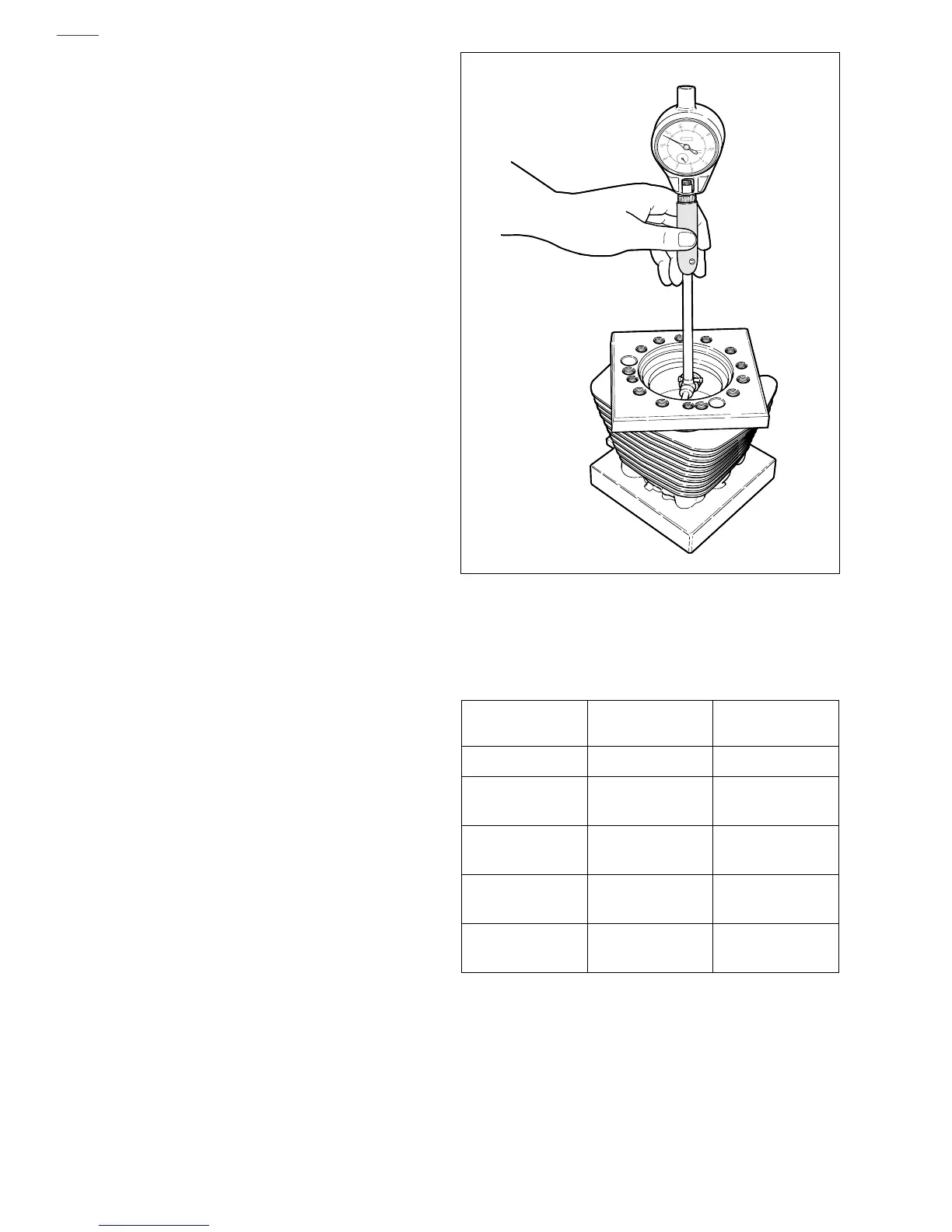
Measuring Cylinder Bore
1. Remove any burrs from the cylinder gasket surfaces.
2. See Figure 3-32. Install a head and base gasket, and
CYLINDER TORQUE PLATES (Part No. HD-33446A)
and XL EVOLUTION TORQUE PLATE BOLTS (Part No.
HD-33446-86). Tighten the bolts using the same method
used when installing the cylinder head screws. See 3.5
CYLINDER HEAD.
NOTE
Torque plates, properly tightened and installed with gaskets,
simulate engine operating conditions. Measurements will
vary as much as 0.001 in. (0.025 mm) without torque plates.
3. Take cylinder bore measurement in ring path, starting
about 1/2 in. (12.7 mm) from top of cylinder, measuring
from front to rear and then side to side. Record readings.
4. Repeat measurement at center and then at bottom of
ring path. Record readings. This process will determine if
cylinder is out-of-round (or “egged”) and will also show
any cylinder taper or bulge.
5. See Tabl e 3-6. If cylinder is not scuffed or scored and is
within service limit, see FITTING CYLINDER TO PIS-
TON on page 3-27.
NOTE
If piston clearance exceeds service limit, cylinders should be
rebored and/or honed to next standard oversize, and refitted
with the corresponding piston and rings. Do not fit piston
tighter than 0.0007 in. (0.0178 mm). See 3.1 SPECIFICA-
TIONS.
Figure 3-32. Measuring Cylinder Bore Using Torque
Plates (Part No. HD-33446A)
Table 3-6. Cylinder Bore
Service Wear Limits
BORE SIZES IN. MM
Standard Bore 3.5008 88.9203
0.005 in. OS Bore
(0.127 mm)
3.5050 89.0270
0.010 in. OS Bore
(0.254 mm)
3.5100 89.1540
0.020 in. OS Bore
(0.508 mm)
3.5200 89.4080
0.030 in. OS Bore
(0.762 mm)
3.5300 89.6620
b0306x3x
 Loading...


