2002 Buell S3T: Electrical 7-7
HOME
IGNITION COIL 7.4
GENERAL
See Figure 7-7 The ignition coil is mounted on the frame
underneath the fuel tank and behind the steering neck.
See Figure 7-7 The ignition coil (12) is a pulse-type trans-
former. Internally, the coil consists of primary and secondary
windings with a laminated iron core. The contents are sealed
in a waterproof insulating compound. The ignition coil is not
repairable. Replace the unit if it fails.
The low-voltage ignition primary circuit consists of the coil pri-
mary winding, ignition module (22) and battery. When the cir-
cuit is closed, current flows through the coil primary winding
creating a strong magnetic field in the iron core of the ignition
coil.
When the ignition module receives a signal from the cam
position sensor (7) and trigger rotor (8), the ignition module
interrupts (opens) the ignition primary circuit, which causes
the magnetic field in the coil core to collapse suddenly.
The collapsing magnetic field induces a high-voltage electri-
cal discharge in the ignition secondary circuit, which consists
of the coil secondary winding, spark plug cables and spark
plugs (11). The high-voltage discharge produces a spark to
bridge the electrode gap of each spark plug.
The ignition coil fires each spark plug independently on the
compression stroke of each cylinder.
REMOVAL
11WARNING1WARNING
To protect against shock and accidental start-up of vehi-
cle, disconnect the negative battery cable before pro-
ceeding. Inadequate safety precautions could result in
death or serious injury.
1. Disconnect negative battery cable from battery.
2. Remove seat. See 2.35 SEAT.
11WARNING1WARNING
The gasoline in the fuel supply line downstream of the
fuel pump is under high pressure (49 psi [338 kPa]). To
avoid an uncontrolled discharge or spray of gasoline,
always purge the system of high pressure gas before
removing fuel tank. Gasoline is extremely flammable and
highly explosive. Inadequate safety precautions could
result in death or serious injury.
3. Purge fuel line and remove fuel tank.
4. See Figure 7-7 Disconnect the spark plug cables from
the coil plug posts (1, 2).
5. Detach connector (7) [83].
6. Remove two screws and washers to drop coil from
frame.
Figure 7-4. Ignition Coil Location
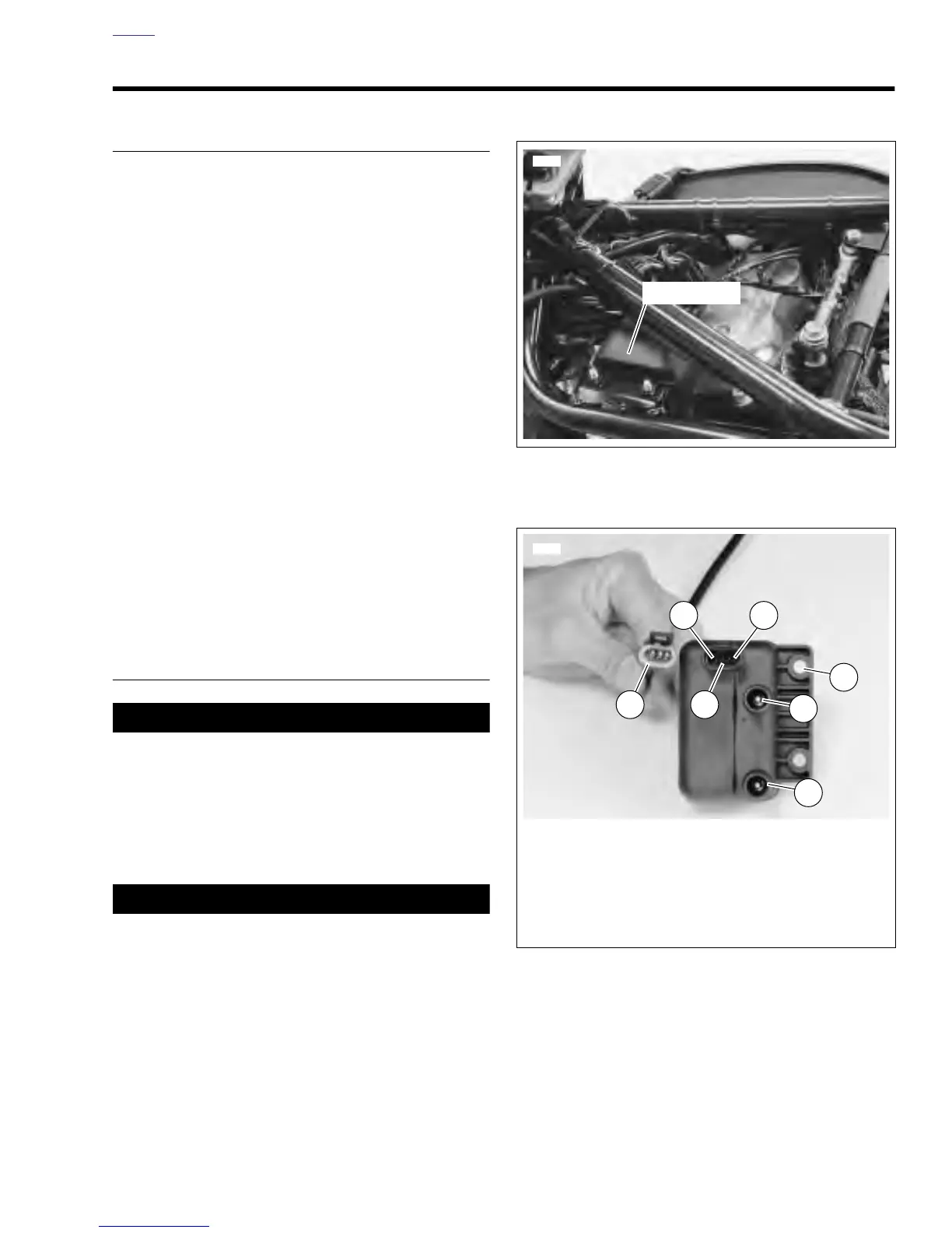
Figure 7-5. Ignition Coil
1
6766
2
46
5
1. Rear Cylinder Post
2. Front Cylinder Post
3. Screw and Washer Location
4. Coil Pin A (Rear Cylinder)
5. Coil Pin B (12 VDC)
6. Coil Pin C (Front Cylinder)
7. Connector [83]
7
3