2002 Buell S3T: Chassis 2-25
HOME
REAR BRAKE MASTER CYLINDER 2.13
REMOVAL
1. See Figure 2-32. Drain brake fluid into a suitable con-
tainer. Discard of used fluids according to local laws.
a. Remove cap from rear caliper bleeder valve. Open
bleeder valve (metric) about 1/2 turn.
b. Install a length of plastic tubing over caliper bleeder
valve. Place free end in a suitable container.
c. Pump brake pedal to drain brake fluid.
d. Tighten bleeder valve (metric) to 3-5 ft-lbs (4-7 Nm).
Reinstall cap.
11WARNING1WARNING
Any leak in brake system will adversely affect brake
operation. Damaged banjo bolt seating surfaces will leak
when reassembled. Prevent damage to seating surfaces
by carefully removing brake line components. Failure to
comply could result in death or serious injury.
2. See Figure 2-33. Remove banjo bolt (1) (metric) and two
banjo washers (2) to detach brake line (3) from master
cylinder (4). Discard banjo washers.
3. See Figure 2-34. Disconnect push rod from brake pedal
turn buckle (4).
a. Spin locknut (3) away from top surface of turn
buckle.
b. Turn rod adjuster (2) to free rod from turn buckle (4).
4. See Figure 2-35. Remove two screws (2) (metric) to
detach master cylinder (3) from frame.
5. See Figure 2-36. Detach remote reservoir.
a. Remove top or bottom clamp on hose connected to
master cylinder.
b. Remove screw to detach reservoir from frame if nec-
essary.
DISASSEMBLY
NOTE
Do not disassemble master cylinder unless problems are
experienced. Discard all seals during the disassembly proce-
dure. Install a complete rebuild kit upon assembly.
1. See Figure 2-37. Slide rubber boot on rod assembly (3)
away from master cylinder body (1).
2. Depress rod assembly (3) and remove internal snap ring
(2). Discard snap ring.
3. Remove piston assembly (4) from master cylinder body.
Figure 2-32. Rear Caliper Bleeder Valve (Metric)
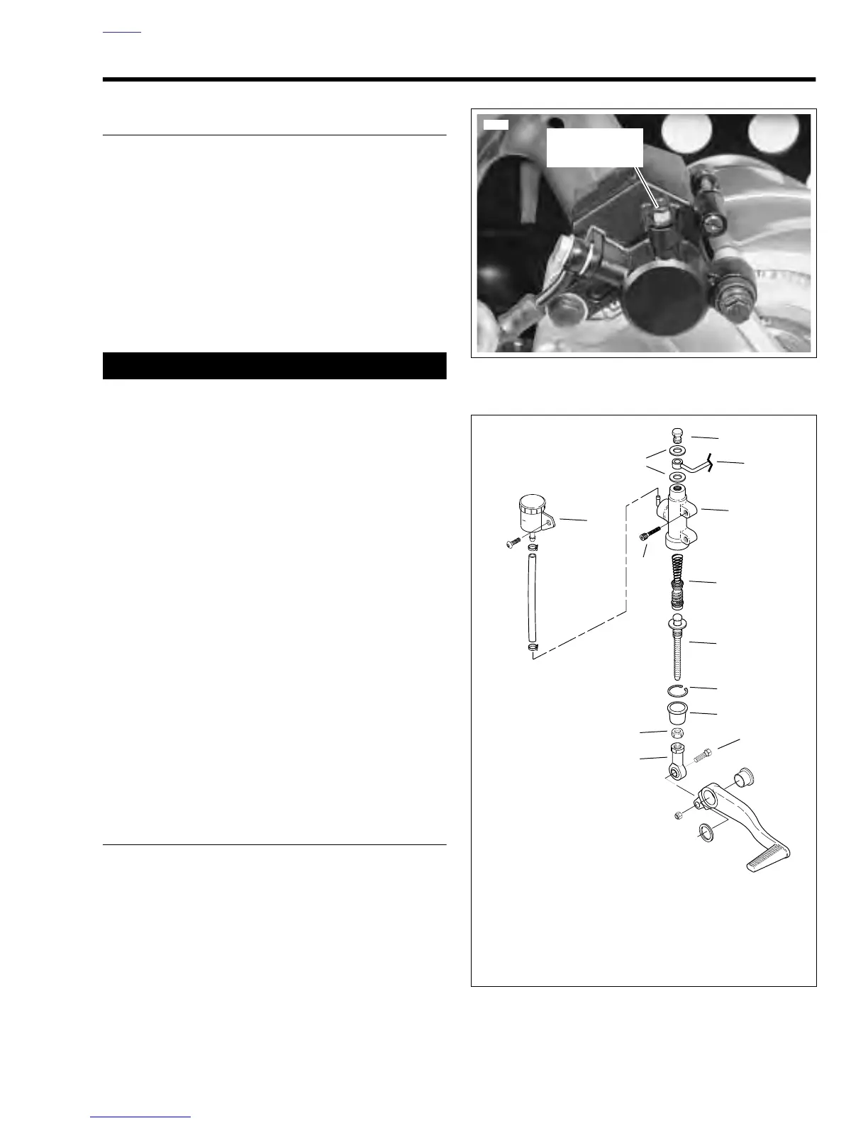
Figure 2-33. Rear Master Cylinder Assembly
6483a
Bleeder Valve
(metric)
1
2
3
4
6
8
7
9
10
11
12
13
5
1. Banjo Bolt (metric)
2. Banjo Washers (2)
3. Brake Line
4. Master Cylinder
5. Screw (2) (metric)
6. Piston Assembly
7. Push Rod
8. Snap Ring
9. Rubber Boot
10. Locknut
11. Turnbuckle
12. Screw
13. Remote Reservoir
b0474x2x