7-28 2002 Buell S3T: Electrical
HOME
VOLTAGE REGULATOR 7.10
GENERAL
The voltage regulator attaches to a mounting plate at the
front of the crankcase. The voltage regulator is not repairable.
Replace the unit if it fails.
Positive Lead
A red wire with a female bullet connector leads from the AUX
terminal of the main circuit breaker to beneath the oil pump.
Here it connects with a male bullet connector from the volt-
age regulator. The two joined wires are cable strapped to the
oil pump.
Negative Lead
A
new
18 gauge ground wire is spliced at one end to SPL2
and terminated at the other end by a star-washer type ring
terminal. The ring terminal attaches to the bottom of the volt-
age regulator.
REMOVAL
11WARNING1WARNING
To protect against shock and accidental start-up of vehi-
cle, disconnect the negative battery cable before pro-
ceeding. Inadequate safety precautions could result in
death or serious injury.
1. Disconnect negative battery cable from battery.
CAUTION
When disconnecting the alternator stator wiring, pull
apart the connector by firmly grasping both connector
halves. Do not pull on leads or damage to the wires and/
or terminals may result.
2. See Figure 7-30. Locate voltage regulator connector [46]
near the oil pump. Disconnect from alternator stator wir-
ing.
NOTE
The black charging wire, formerly loose, is now part of the
harness and connector [46].
3. Remove screws and washers.
4. Remove and discard voltage regulator.
5. If necessary, detach mounting bracket by removing
screw, washers and nut.
INSTALLATION
1. See Figure 7-31. Attach
new
voltage regulator to bracket
using screws and washers.
2. Connect voltage regulator connector [46] to alternator
stator wiring. Bundle excess wiring in front of oil pump.
Secure bundle to oil pump using a
new
cable strap.
3. Route ground wire to gold post on main circuit breaker.
Secure wire to frame with
new
cable straps.
4. Install tail section, fuel tank bolt and seat. See 2.33 TAIL
SECTION.
5. Connect negative battery cable to battery.
6. Test charging system. See 7.8 CHARGING SYSTEM.
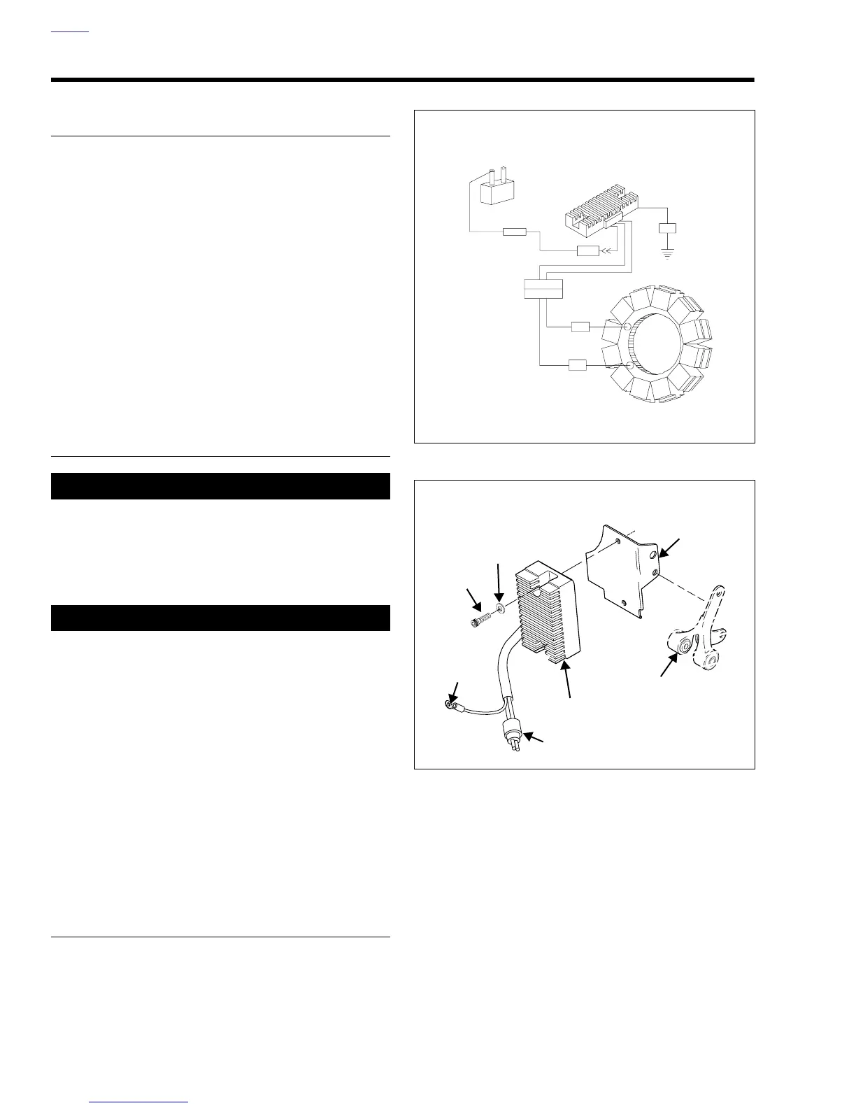
Figure 7-30. Voltage Regulator Wiring
Figure 7-31. Voltage Regulator
30A
BK
BK
BK
RD
RD
Main Circuit
Breaker
Voltage
Regulator
Stator
[46]
b0838x7x
Screws (2)
Washers (2)
Connector [46]
Voltage
Regulator
Ground
Wire Ring
Terminal
Voltage Regulator
Mount Bracket
Header
Support Mount