2002 Buell S3T: Drive/Transmission 6-33
HOME
TRANSMISSION INSTALLATION AND
SHIFTER PAWL ADJUSTMENT 6.13
Verify that all parts have been properly installed, as described
earlier in this section under:
●
6.12 RIGHT TRANSMISSION CASE BEARINGS
●
6.10 MAIN DRIVE GEAR
●
6.9 MAINSHAFT AND COUNTERSHAFT
●
6.8 SHIFTER FORKS AND DRUM
1. Carefully insert transmission into case opening. Position
the assembly so that the mainshaft enters fifth gear, and
so that the countershaft and drum shifter shaft enter their
respective bearings.
2. See Figure 6-58. Install access door.
a. Apply a few drops of LOCTITE THREADLOCKER
243 (blue) to the five access door mounting bolts
with captive washers (7).
b. Insert the bolts with captive washers (7) through
access door into tapped holes in right transmission
case.
c. Tighten to 13-17 ft-lbs (18-23 Nm).
3. Lift pawl (5) over drum pins and place shifter shaft
assembly (6) on studs at transmission case. Loosely
install a washer (11) and locknut (3) on each stud.
4. Attach loop of spring (1) over and into groove in post (2).
5. Install detent plate.
a. Place detent plate (8) over drum pins.
b. Rotate plate until blind holes in plate align with pins
in end of shifter fork drum.
c. Install
new
retaining ring (9) using SHIFT DRUM
RETAINING RING INSTALLER (Part No. HD-
39151).
d. Verify that retaining ring is fully engaged with drum
groove.
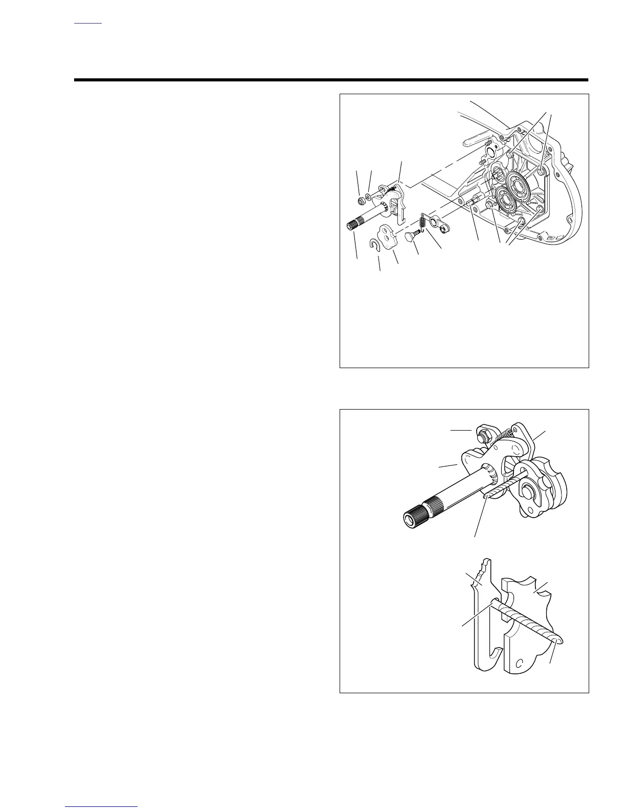
6. See Figure 6-59. Align shifter shaft.
a. Place transmission in third gear.
b. Place a No. 32 drill bit (0.116 in. dia.) through hole in
detent plate (3), and between pawl (2) and drive pin
at end of shifter drum shaft.
c. Push down top of crank (4) to remove all clearance
between pawl and drill bit; this will correctly align
pawl to shift drum pins (do not push down with too
great a force, as this might cause the shifter drum to
rotate).
d. With bit in place, tighten shifter shaft assembly bot-
tom locknut (1) first to 90-110
in-lbs (10-12 Nm).
Then, tighten shifter shaft assembly top locknut (1)
to the same torque.
e. Remove drill bit.
7. See Figure 6-37. Place new quad ring (17) over
threaded end of fifth gear (21), and position next to the
gear taper. Install spacer (16) over threaded end of fifth
gear with chamfered end toward quad ring. Slide spacer
up against bearing (19).
Figure 6-58. Installing Access Door
Figure 6-59. Shifter Shaft Assembly Alignment
7. Bolt with Captive
Washer (5)
8. Detent Plate (Typi-
cal)
9. Retaining Ring
10. Washer (2)
b0153x6x
3 10
5
6
9
8
4
1
2
7
7
1. Spring
2. Post
3. Locknut (2)
4. Detent Screw
5. Pawl
6. Shifter Shaft Assembly
b0135x6x
1
2
4
2
3
No. 32 Drill Bit (0.116 in. dia.)
Drill bit
1. Locknut (2)
2. Pawl
3. Detent Plate
(Typical)
4. Crank
5. Shifter Drum Pin
5