6-34 2002 Buell S3T: Drive/Transmission
HOME
8. Install seal.
a. Coat lips of seal (15) with SPORT-TRANS FLUID.
b. Position seal over spacer (16) with lips of seal
toward case.
c. Gently tap seal into bore of case until the outside of
seal is flush with outer edge of bore.
NOTE
It is acceptable to recess seal to about 0.030 in. (0.762 mm)
below outer edge of bore. Seal recession will be limited by
seal bottoming against retaining ring (18).
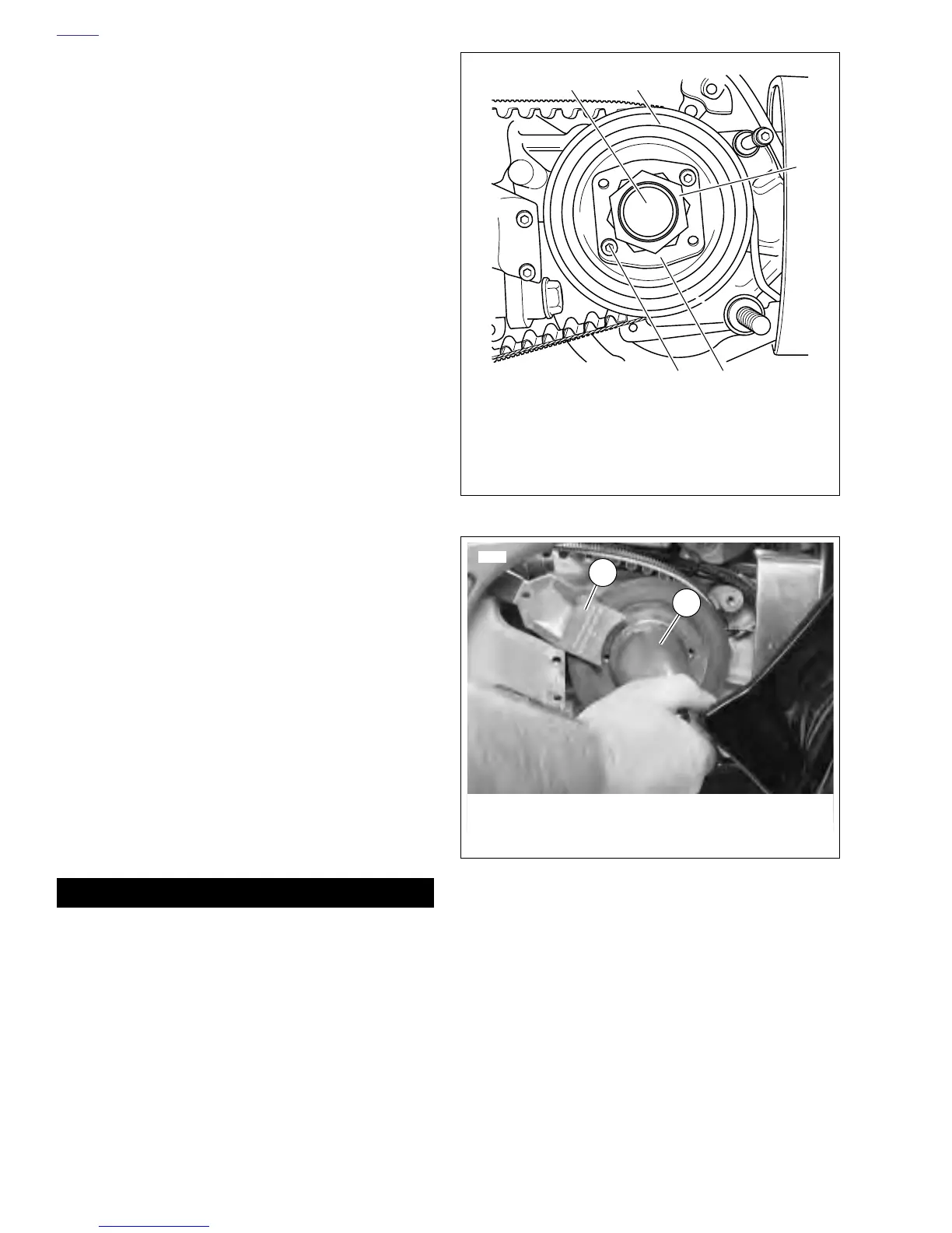
9. See Figure 6-60. Increase belt deflection by loosing rear
axle and moving rear wheel forward. Install transmission
sprocket (2) with secondary drive belt onto main drive
gear shaft (1).
10. Place transmission in neutral.
11. Apply a few drops of LOCTITE THREADLOCKER 262
(red) to the left-hand threads of transmission sprocket
nut (3). Position nut with washer-faced side facing trans-
mission sprocket. Turn the nut counterclockwise to
install it onto main drive gear shaft.
a. See Figure 6-61. Install SPROCKET HOLDING
TOOL (1) (Part No. HD-41321) as shown. Use
MAINSHAFT LOCKNUT WRENCH (2) (Part No.
HD-94660-37B) and a torque wrench to tighten
sprocket nut to 50 ft-lbs (68 Nm) INITIAL torque,
ONLY.
b. See Figure 6-62. Scribe a line on the transmission
sprocket nut and continue the line on the transmis-
sion sprocket as shown.
c. Tighten the transmission sprocket nut an additional
30°-40°.
d. See Figure 6-60. Install lockplate (4) over nut (3) so
that two of lockplate’s four drilled holes (diagonally
opposite) align with sprocket’s (2) two tapped holes.
NOTE
The lockplate has four screw holes and can be turned to
either side, so you should be able to find a position without
having to additionally tighten the nut. If you cannot align the
screw holes properly, the nut may be additionally TIGHT-
ENED until the screw holes line up, but do not exceed 45° as
specified above. Never LOOSEN nut to align the screw holes.
e. See Figure 6-62. If lockplate will not align with holes,
tighten nut to 45° maximum.
11WARNING1WARNING
Maximum allowable tightening of sprocket nut is 45° of
counterclockwise rotation, after initially tightening to 50
ft-lbs. Do not loosen sprocket nut while attempting to
align the screw holes. If you cannot align lockplate and
sprocket screw holes, nut may be additionally tightened
45° as specified above. Tightening too much or too little
may cause the nut to come loose during vehicle opera-
tion which may cause an accident which could result in
death or serious injury.
12. If you cannot align lockplate and sprocket screw holes,
nut may be additionally tightened until screw holes align.
Figure 6-60. Transmission Sprocket
Figure 6-61. Transmission Sprocket Tightening
1. Main Drive Gear Shaft
2. Transmission Sprocket
3. Transmission Sprocket Nut (Left-Hand Threads)
4. Lockplate
5. Socket Head Screw (4)
1
3
2
45
b0249x6x
1
6241
2
1. Sprocket Holding Tool (Part No. HD-41321)
2. Mainshaft Locknut Wrench
(Part No. HD-94660-37B)