HOME
4-102 2002 Buell S3T: Fuel System
FUEL PUMP 4.39
REMOVAL
11WARNING1WARNING
The gasoline in the fuel supply line downstream of the
fuel pump is under high pressure (49 psi [338 kPa]). To
avoid an uncontrolled discharge or spray of gasoline,
always purge the system of high pressure gas before
removing fuel tank. Gasoline is extremely flammable and
highly explosive. Inadequate safety precautions could
result in death or serious injury.
1. Purge fuel line and remove fuel tank. See 4.36 FUEL
TANK.
11WARNING1WARNING
An open flame or spark may cause a fuel tank explosion
if all traces of fuel are not purged from the tank. Use
extreme caution when servicing fuel tanks. Gasoline is
extremely flammable and highly explosive. Inadequate
safety precautions could result in death or serious injury.
2. Drain fuel from tank.
a. Using suitable external fuel pump, such as a Gas
Caddy, pump fuel from tank and into suitable clean
container.
b. See instructions for external fuel pump for correct
use.
3. Remove fuel filler cap flange assembly. See 4.36 FUEL
TANK.
4. See Figure 4-89. Remove fuel fitting nut (1).
5. Remove electrical fitting nut (5), washer, sealing washer
and rubber seal (6).
6. Push electrical and fuel fitting studs back into tank.
7. Reach inside fuel filler cap hole and remove pump
assembly.
REPAIR
Fuel Pump Replacement
1. Remove fuel pump assembly from tank.
2. See Figure 4-90. Remove retaining clamp (5) from pump
body (4) using a pair of cutters.
3. Pull pump outlet fitting from pump holder housing (2).
Detach electrical wires (3) and discard old pump.
4. Place new rubber sleeve on new pump’s outlet fitting.
5. Attach both electrical connectors (3) to new pump. Note
that connectors are two different sizes.
6. Press pump fitting outlet into pump holder housing (2).
7. Place a new retaining clamp (5) over pump body. Posi-
tion clamp inside groove (8) on pump holder housing.
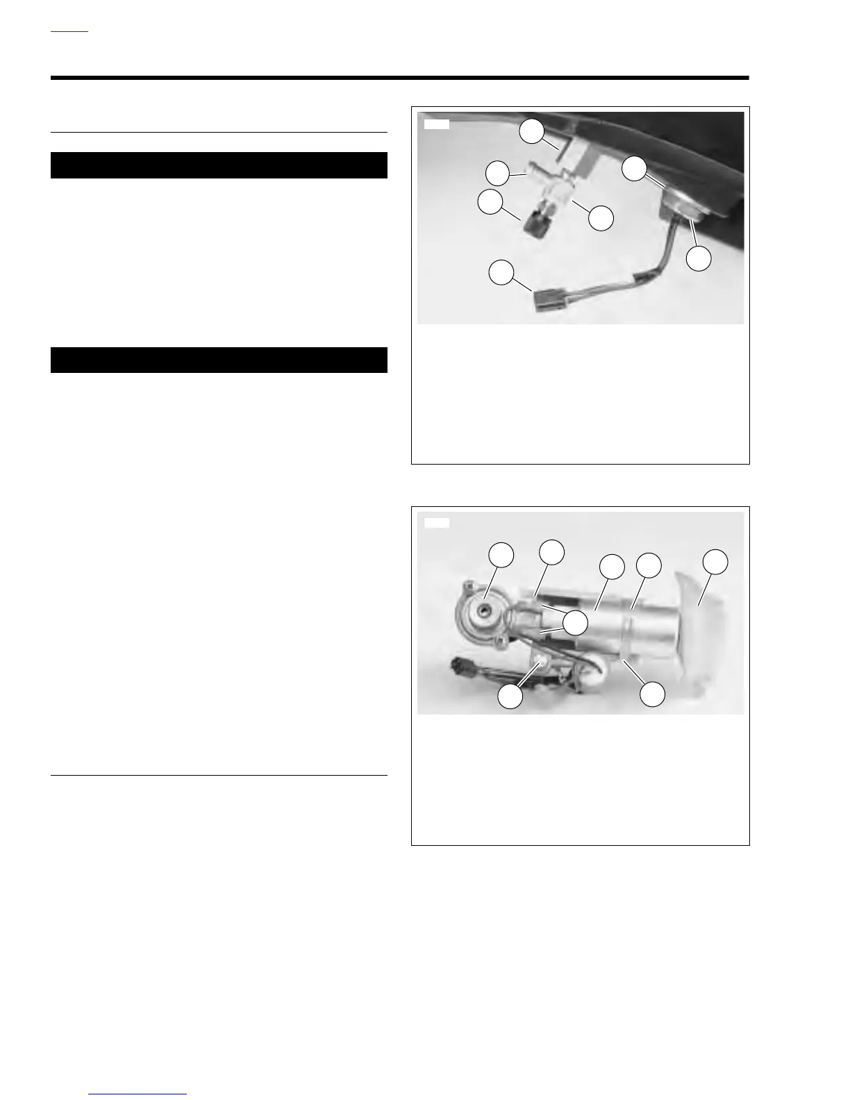
Figure 4-89. Fuel Pump Within Tank
Figure 4-90. Fuel Pump Assembly
6882
1
2
3
4
1. Fuel Fitting Nut
2. Fuel Outlet with attached Schraeder Valve
3. Protective Cap
4. Fuel Pump Connector [86]
5. Electrical Fitting Nut
6. Electrical Fitting Washer, Sealing Washer
and Rubber Seal
7. Barb (on Fitting)
6
5
7
6950
1
2
4
5
6
7
3
1. Pressure Regulator
2. Pump Holder Housing
3. Pump Wiring (2 connectors, 2 sizes)
4. Pump Body
5. Retaining Clamp
6. Filter
7. Low Fuel Level Sensor
8. Groove
8