HOME
2-44 2002 Buell S3T: Chassis
11. See Figure 2-72. Working on the right side first, insert
the REAR ISOLATOR REPLACEMENT TOOL (Part No.
B-44623) between mount block and frame. NOTE: Ledge
on tool should engage top of mount block.
CAUTION
Do not alter tool or shim in an attempt to spread frame
further than tool will allow. Failure to comply may result
in frame distortion or damage.
12. Turn nut on rear isolator replacement tool clockwise to
expand frame from swingarm mount block until isolator
can be removed. Nut will stop when limit of travel is
reached.
13. Disengage right side rear isolator from roll pin in frame
by pulling inboard. Remove isolator by pulling out from
5:00 or 6:00 position.
14. Remove rear isolator replacement tool by turning nut
counterclockwise.
15. Remove left side isolator bolt and washer from bearing
adjusting bolt.
16. Remove nut and back out bolt (until flush with the mount
block) from upper rear of muffler Z bracket and swingarm
mount block.
17. Pull frame to left and remove left side isolator from 6:00
or 7:00 position.
INSPECTION
NOTE
If roll pin protrudes beyond specification, check to make sure
it is fully seated. A channel lock pliers may be used to
squeeze/push roll pin in. Protect frame with a shop rag when
using pliers.
See Figure 2-73. Measure isolator roll pin protrusion on both
left and right isolator mounts with calipers or metal rule. Roll
pin should not protrude more than 0.120 in. (3 mm). If roll pin
protrudes more than 0.120 in. (3 mm) file or grind until within
specification; 0.080-0.120 in. (2.032-3.048 mm). Use care
when filing to avoid creating sharp edges.
INSTALLATION
1. On left side of motorcycle, align locator hole with roll pin
and install left rear isolator provided in kit. The left isola-
tor backing plate has an “L” stamped on it.
2. Move to right side of motorcycle. Lower the frame
approximately two inches with the hoist to allow clear-
ance between isolator replacement tool.
3. See Figure 2-72. On right side of motorcycle, insert rear
isolator replacement tool between mount block and
frame.
CAUTION
Do not alter tool or shim in an attempt to spread frame
further than tool will allow. Failure to comply may result
in frame distortion or damage.
4. Turn nut on tool clockwise to expand frame from mount
block. Nut will stop when limit of travel is reached.
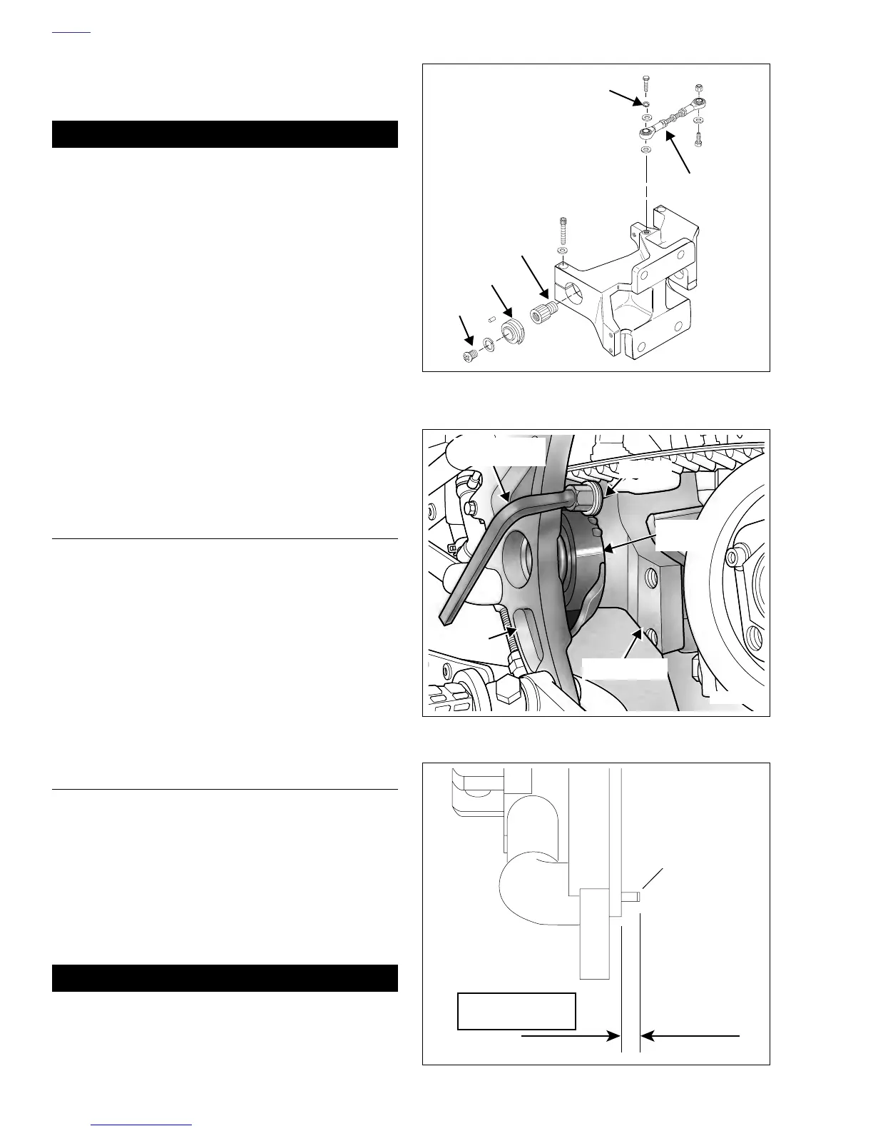
Figure 2-71. Mount Block
Figure 2-72. Rear Isolator Replacement Tool In Use
Figure 2-73. Measuring Roll Pin Protrusion
b0202c3x
Rear Tie Bar
Isolator
TORX Bolt
Lockwasher
Isolator
Bearing
Adjusting
Bolt
b0869x2x
Ledge
Mount Block
Frame
Replacement
Tool (B-44623)
Rear
Isolator
0.080-0.120 in.
(2.032-3.048 mm)
Pin
 Loading...


