HOME
2-54 2002 Buell S3T: Chassis
ASSEMBLY/INSTALLATION
Clutch Cable-Lower
1. See Figure 2-83. Install O-ring (8) over cable end fitting
(9) of clutch cable lower section. Turn fitting clockwise to
install into primary cover (11). Tighten to 3-7 ft-lbs (4-
12 Nm).
2. Fit coupling (16) over cable end. Place hook of ramp
around coupling button and rotate assembly counter-
clockwise until tang on inner ramp (15) fits in slot of pri-
mary cover (11).
3. Thread nut (5) on adjusting screw (12) until slot of screw
is accessible with a screwdriver. Fit nut hex into recess of
outer ramp (6) and turn adjusting screw counter-clock-
wise.
4. If not yet performed, route clutch cable to hand control.
a. See Figure 2-85. Route cable along left side of pri-
mary chaincase and up through clamp on front iso-
lator tie bar.
b. Continue above and behind lower triple clamp,
between left fork leg and steering neck.
c. Route cable across front of upper triple clamp to
hand grip.
5. With clutch cable upper section connected to clutch
lever, check primary chain tension. Adjust if necessary.
See 1.12 PRIMARY CHAIN.
6. Adjust clutch. See 1.9 CLUTCH.
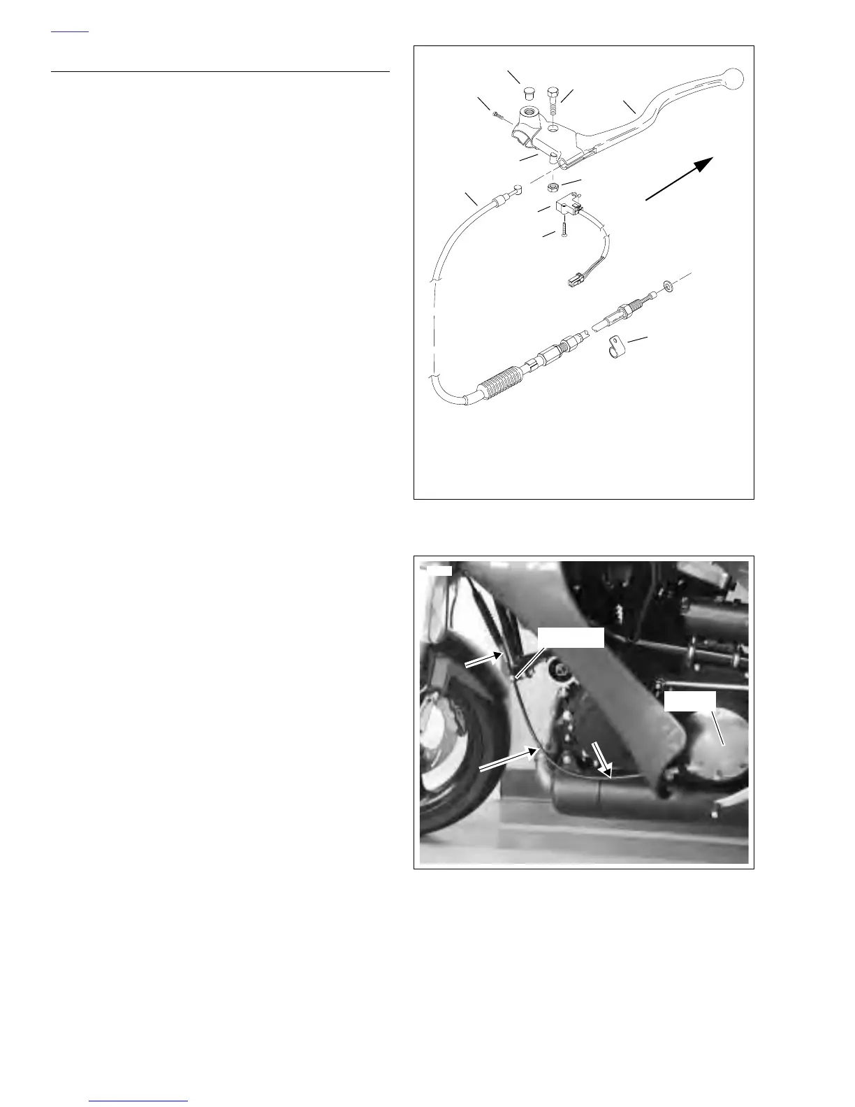
Clutch Hand Control
1. See Figure 2-84. Attach clutch clamp (5) as follows.
a. Slide clamp over handlebar.
b. Install left switchgear housing. See 7.5 HANDLE-
BAR SWITCHES.
c. Place clamp next to switchgear housing. Fasten to
handlebar with screw (4) (metric). Tighten to 30-
35 in-lbs (3-4 Nm).
d. Install a new left handgrip. See 2.26 HANDLE-
BARS.
2. Connect end of clutch cable upper section to clutch han-
dlever. Position lever within clutch clamp.
3. Apply small amount of LOCTITE ANTI-SEIZE LUBRI-
CANT to bolt (2). Attach handlever with bolt (2) (metric)
and nut (6) (metric).
4. Attach clutch switch (7) with screw (8).
5. If not yet performed, route clutch cable to primary cover.
a. Route cable from hand grip across front of upper tri-
ple clamp.
b. Continue to left side, down between left fork leg and
steering neck, above lower triple clamp.
c. See Figure 2-85. Route cable down left side of bike,
through clamp, along primary chaincase to clutch.
6. With clutch cable lower section connected to primary
cover, adjust clutch. See 1.9 CLUTCH.
Figure 2-84. Clutch Hand Control
Figure 2-85. Clutch Cable Routing, Lower
b0406x2x
3
1. Clutch Handlever
2. Bolt (metric)
3. Plug
4. Screw (metric)
5. Clutch Clamp
6. Nut (metric)
7. Clutch Switch
8. Screw
9. Clutch Cable
10. Cable Clamp
1
2
4
9
8
7
6
10
Remove switch (7)
5
8307
Clutch
Clamp