HOME
2-58 2002 Buell S3T: Chassis
ASSEMBLY/INSTALLATION
Muffler
1. If removed, install exhaust header.
2. See Figure 2-91. If removed, install Z-bracket.
a. Install rear muffler mounts and mount spacers on
swingarm mount block.
b. Attach Z-bracket with bolts, locknuts and washers.
Bolt heads install on opposite side of the swingarm
mount block from Z-bracket. Tighten to 22-24 ft-lbs
(30-33 Nm).
3. See Figure 2-89. If removed, attach header support
mount to crankcase.
a. Insert two front muffler mounts and mount spacer
into muffler support.
b. Install nuts and washers securing header support
mount to voltage regulator bracket and crankcase.
c. Attach header support mount to crankcase using
two upper bolts. Tighten to 30-33 ft-lbs (41-45 Nm).
4. Coat inside of muffler inlet with PERMATEX ULTRA-
COPPER HIGH TEMP RTV SILICON GASKET material.
NOTE
If necessary, use a fiber hammer to fit muffler on header.
5. Place a new muffler clamp over muffler inlet. Place muf-
fler and clamp on end of exhaust header. Snug clamp
but do not tighten.
11WARNING1WARNING
Before tightening muffler hardware, position muffler to
provide adequate clearance from rear shock absorber,
side stand spring post and rear tire. Failure to provide
adequate clearance may cause loss of control during
motorcycle operation which could result in death or seri-
ous injury.
6. See Figure 2-88. Position muffler and install to rear
mounting support and weldnuts in rear muffler straps
with two sets of bolts, washers and locknuts. Tighten to
22-24 ft-lbs (30-33 Nm).
7. See Figure 2-89. Secure muffler to header support
mount with bolt, locknut and washers. Tighten to 22-
24 ft-lbs (30-33 Nm).
8. When only the muffler is being replaced, tighten muffler
clamp to 40-45 ft-lbs (54-61 Nm). If also installing the
exhaust header, leave muffler clamp loose.
Exhaust Header
NOTE
Muffler hardware must be tightened before tightening exhaust
header hardware.
1. See Figure 2-93. Install new exhaust port gaskets (5)
and exhaust clamp retaining rings (2).
2. Slide exhaust header clamps (3) over ends of exhaust
header (1).
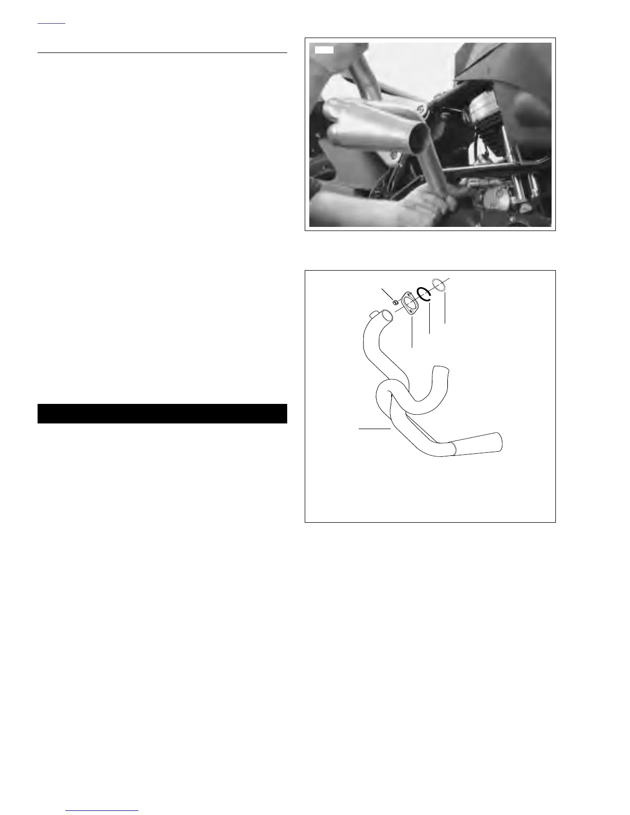
3. See Figure 2-92. Slide exhaust header under frame by
positioning as shown, threading oxygen sensor wire
under frame.
4. Position rear end of exhaust header in port. Do not install
exhaust header clamp over port.
5. Rotate exhaust header so that front end of exhaust
header is in position at front port to cylinder head.
6. See Figure 2-93. Fasten exhaust header to cylinder
heads with exhaust header clamps and nuts. Tighten the
four exhaust header nuts to 6-8 ft-lbs (8-11 Nm) using
SNAP-ON SWIVEL SOCKET (Part No. PFSX916).
7. Install oxygen sensor to header if removed. Apply LOC-
TITE ANTI-SEIZE LUBRICANT to threads of sensor and
install to exhaust header. Tighten sensor to 42-45 ft-lbs
(57-61 Nm). Attach oxygen sensor connector [137].
Secure wiring and sensor with new cable ties.
8. Tighten muffler clamp to 40-45 ft-lbs (54-61 Nm).
9. Install right fairing lower. See 2.38 FAIRING LOWERS.
Figure 2-92. Exhaust Header Positioning (Typical)
Figure 2-93. Exhaust Header
6813
1. Exhaust Header
2. Exhaust Header Nut (4)
3. Exhaust Header Clamp (2)
4. Exhaust Clamp Retaining Ring (2)
5. Exhaust Port Gasket (2)
b0676x2x
1
5
4
3
2













 To Next Page