3-30 2002 Buell S3T: Engine
HOME
ASSEMBLY/INSTALLATION
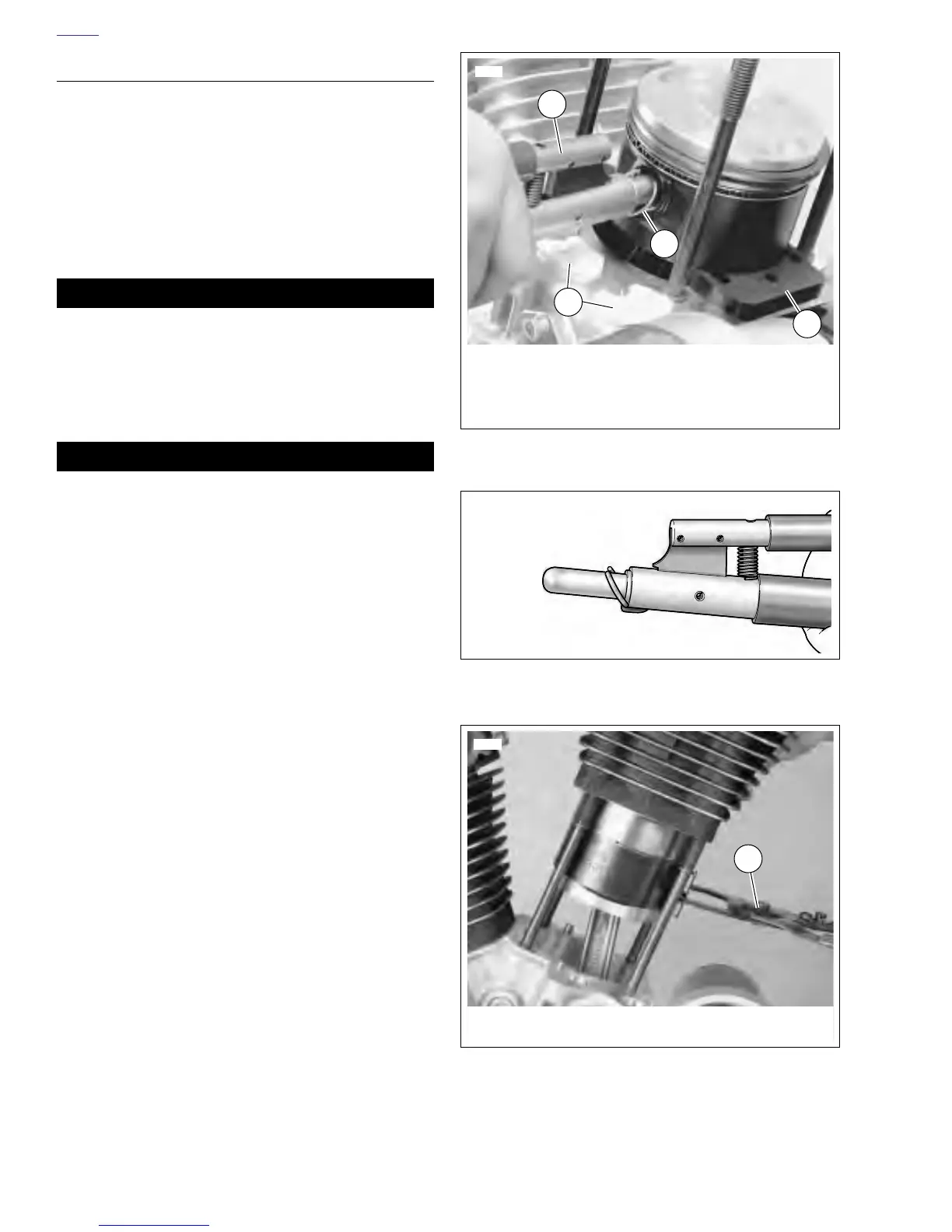
1. See Figure 3-40. Place PISTON SUPPORT PLATE (3)
(Part No. HD-42322) around connecting rod.
2. Install piston assembly over connecting rod.
NOTE
New 1203cc pistons must be installed with the arrow, at the
top of the piston, pointing towards the front of the engine.
3. Install piston pin.
11WARNING1WARNING
The piston pin retaining rings are highly compressed in
the ring groove and may “fly out” with considerable force
when pried out of the groove. Always wear safety
glasses or goggles while removing or installing retaining
rings. Failure to comply could result in death or serious
injury.
CAUTION
Always use new retaining ring. Make sure retaining ring
groove is clean and that ring seats firmly in groove. If it
does not, discard the ring. Never install a used retaining
ring or a new one if it has been installed and then
removed for any reason. A loosely installed ring will
come out of the piston groove and damage cylinder and
piston beyond repair.
4. See Figure 3-40. Install new piston pin retaining rings (1)
using PISTON PIN RETAINING RING INSTALLER (2)
(Part No. HD-34623B). Place new retaining ring on tool
with gap pointing up. See Figure 3-41.
NOTE
Make sure the ring groove is clean. Ring must be fully seated
in the groove with the gap away from the slot at the bottom.
5. See Figure 3-36. Make sure the piston ring end gaps are
properly positioned as shown.
6. Remove PISTON SUPPORT PLATE.
7. Lubricate cylinder wall, piston, pin and rod bushing with
engine oil.
8. Turn engine until piston is at top dead center.
9. See Figure 3-42. Compress the piston rings using PIS-
TON RING COMPRESSOR (Part No. HD-96333-51C).
10. Remove protective sleeves from cylinder studs. Install a
new cylinder base gasket. Make sure the piston does not
bump the studs or crankcase.
11. Install cylinder over piston.
12. Remove PISTON RING COMPRESSOR.
13. Assemble cylinder head. See 3.5 CYLINDER HEAD.
14. Install cylinder head. See 3.5 CYLINDER HEAD.
15. Install assembled engine. See 3.4 INSTALLING THE
ENGINE.
Figure 3-40. Installing Piston Retaining Rings
Figure 3-41. Aligning Retaining Ring
Figure 3-42. Compressing Piston Rings
1
7070
1. Piston Pin Retaining Ring
2. Piston Pin Retaining Ring Installer
3. Piston Support Plate
4. Plugged Lifter Bores
3
2
4
b0382x3x
3535c
1
1. Piston Ring Compressor (Part No. HD-96333-51C)
 Loading...


