Appendix B, Wiring B-3
HOME
face straight upward. When correctly positioned, the
locking bar fits snugly in the space between the contact
band and the core crimp tails.
4. Strip lead removing 5/32 in. (4.0 mm) of insulation. Insert
wires between crimp tails until ends make contact with
locking bar. Verify that wire is positioned so that short
pair of crimp tails squeeze bare wire strands, while long
pair folds over insulation material.
5. Squeeze handle of crimp tool until tightly closed. Tool
automatically opens when the crimping sequence is
complete. Raise up locking bar and remove contact.
NOTE
Inspect the quality of the core and insulation crimps. Distor-
tion should be minimal.
Figure B-2. 3-pin Locking Wedge Orientation
x0014a7x
Socket
Housing
Pin
Housing
Arrow points to
External Latch
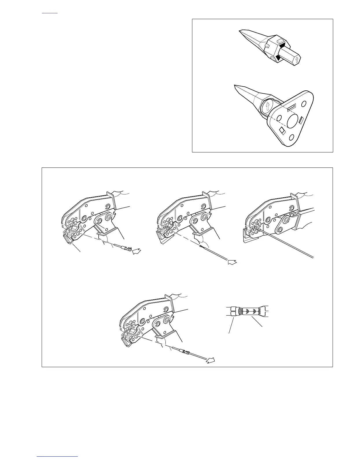
Figure B-3. Deutsch Crimping Procedure
1. Insert contact through middle
hole of locking bar.
2. Insert stripped lead until it
contacts locking bar.
3. Close and squeeze crimp tool.
4. Raise locking bar and
remove contact.
5. Inspect quality of core and
insulation crimps.
x0007b7x
Locking Bar
Insulation Crimp
Core Crimp