4-106 2002 Buell S3T: Fuel System
HOME
INSTALLATION
1. Apply a thin coat of clean engine oil to top and bottom
injector O-rings.
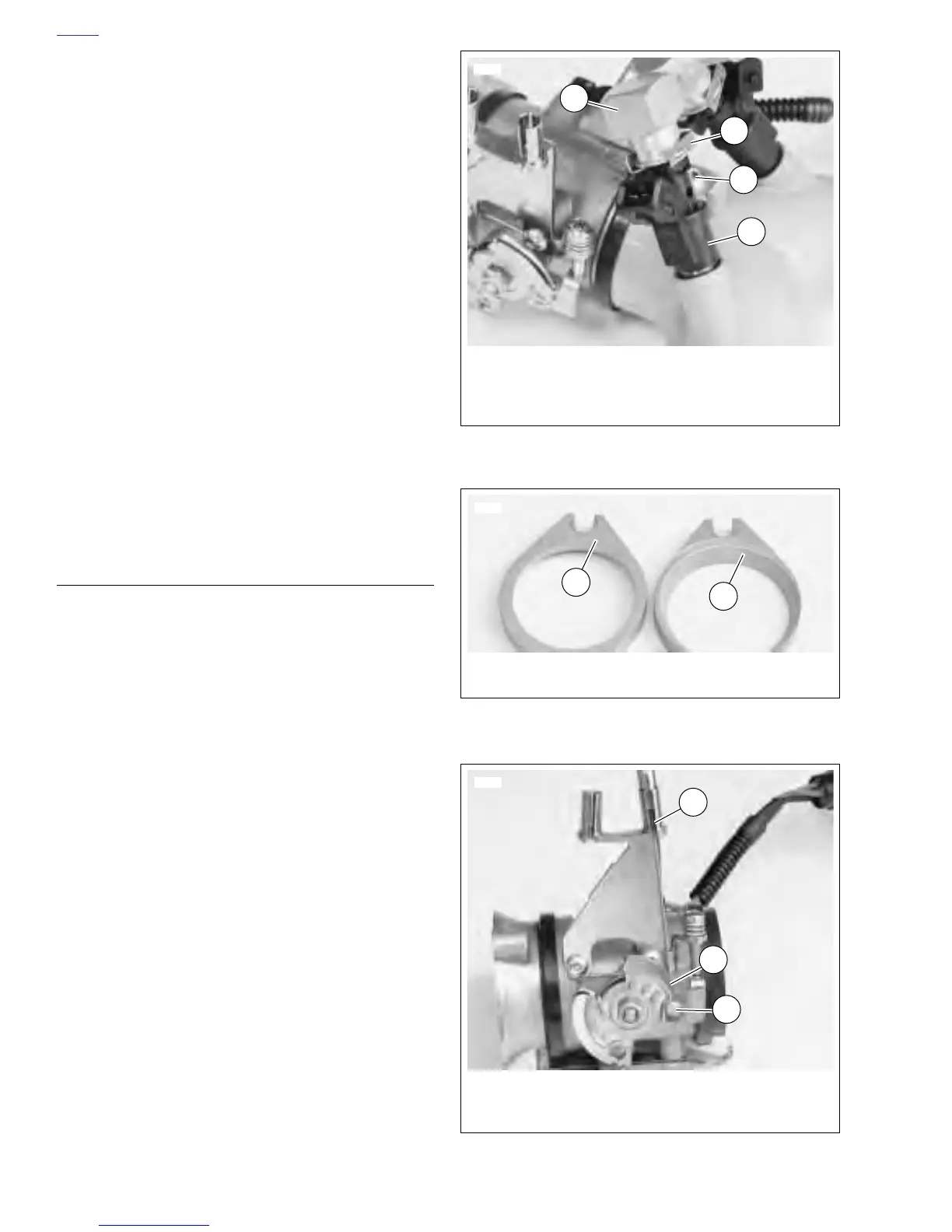
2. See Figure 4-97. Install fuel injectors.
a. Place an O-ring on each side of injector.
b. Install both injectors (4) into intake manifold.
c. Press the fuel rail (1) onto the top of the injectors.
d. Secure the fuel rail to the manifold with screw (met-
ric). Tighten securely.
3. Snap the injector clips (2) over the flange on the fuel rail
outlet and into the top grove in the injector.
4. Install throttle body and intake manifold. See INSTALLA-
TION.
TESTING
1. Remove air cleaner cover.
2. Conduct test.
a. With throttle held wide open, turn key ON for two
seconds.
b. Turn key OFF for two seconds.
c. Repeat Steps A and B five consecutive times.
Replace fuel injectors if there is any evidence of raw
fuel in throttle bottle manifold.
3. Install air cleaner cover.
INSTALLATION
NOTE
If only installing front portion of throttle manifold, begin instal-
lation with Step 3.
1. See Figure 4-98. Install front and rear intake flanges
onto manifold with the counterbore facing out. Each
intake flange is labeled and the pieces are not inter-
changeable.
2. Place a new seal in each intake flange with the beveled
side against the counterbore.
3. See Figure 4-99. Attach both throttle cables. Add free-
play to cables if necessary.
a. With the manifold assembly close to the right side of
the bike but not fully installed, place idle control
cable end (1) into hole on guide (2). Wrap the cable
into the channel.
b. Place the end of the cable housing into the bracket
by sliding the cable through the slot (3). Adjust the
cable so it will not dislodge from the bracket.
c. Repeat procedure for the throttle control cable.
d. Verify that the cables are seated in the channels on
the guide. Check that the cable ends are positioned
in the bosses on the cable bracket.
e. Install screw and throttle cable clamps to throttle
cables.
f. Verify operation by turning throttle grip and observ-
ing the cable action and throttle valve movement.
Figure 4-97. Installing Injectors
Figure 4-98. Intake Flanges
Figure 4-99. Idle Control Cable Installation
1. Fuel Rail Assembly
2. Clip (2)
3. Screw
4. Fuel Injector (2)
4
6943
2
1
3
1. Label (F = front cylinder)
2. Counterbore
1
6954
2
1. Cable End
2. Guide
3. Slot
6955
1
2
3