2002 Buell S3T: Electric Starter 5-17
HOME
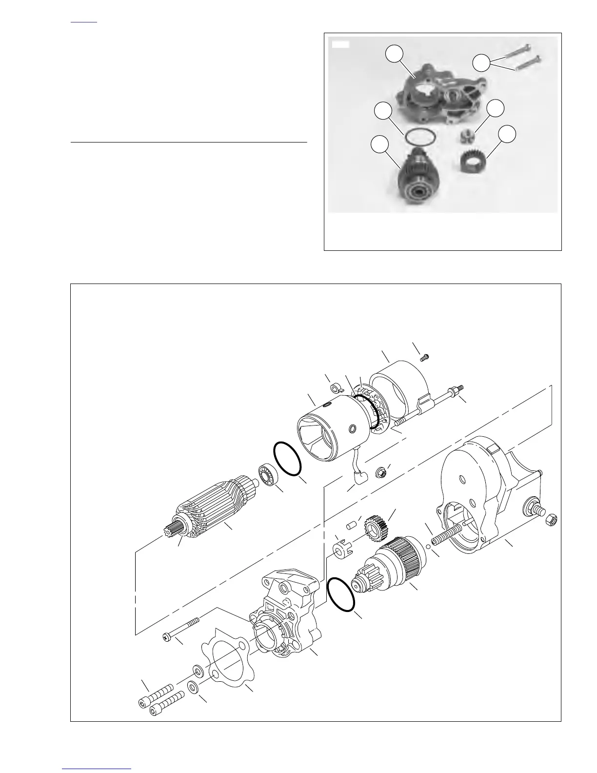
15. See Figure 5-25. Remove two drive housing mounting
screws (6). Remove drive housing (5) from solenoid
housing.
16. Remove drive (1), idler gear (2), idler gear bearing (3),
and O-ring (4) from drive housing (O-ring is located in
drive housing groove).
ASSEMBLY
1. See Figure 5-25. Clean, inspect and lubricate drive
assembly components. Lubricate parts with high temper-
ature grease, such as LUBRIPLATE 110.
2. See Figure 5-26. When installing drive assembly compo-
nents, open end of idler bearing cage (15) faces toward
solenoid.
3. When installing drive housing (10) to solenoid housing
(11), use
new
O-ring (16). Be sure to install return spring
(17) and ball (18).
Figure 5-25. Starter Drive Assembly
4. O-Ring
5. Drive Housing
6. Screws
1. Drive
2. Idler Gear
3. Idler Gear Bearing
1
2
3
4
5
6017
6
Figure 5-26. Starter Assembly
1. Thru-Bolt (2)
2. End Cover Screw
and O-Ring (2)
3. End Cover
4. Brush Holder
5. Brush Spring (4)
6. Armature
7. Field Frame
8. Armature Bearing (2)
9. Drive Housing
Mounting Bolt
10. Drive Housing
11. Solenoid Housing
12. Drive Assembly/
Overrunning Clutch
13. Idler Gear
14. Idler Gear Roller (5)
15. Idler Gear
Bearing Cage
16. O-Ring
17. Return Spring
18. Ball
19. Gasket
20. Washer (2)
21. Mounting Bolt (2)
22. Field Wire
23. O-Ring (2)
24. Field Wire Nut
with Washer (metric)
b0004a5x
21
20
19
10
16
12
18
11
9
15
13
14
17
8
6
8
23
1
23
4
24
22
2
3
5
7