2002 Buell S3T: Drive/Transmission 6-5
HOME
Primary Cover
1. Remove foreign material from magnetic drain plug.
Install plug and tighten to 14-30 ft-lbs (19-41 Nm).
2. Wipe gasket surface clean. Install
new
gasket on pri-
mary cover.
3. See Figure 6-4. Install primary cover and gasket onto left
crankcase half using mounting screws. Tighten screws to
100-120
in-lbs
(11-14 Nm).
4. See Figure 6-1. Install
new
shifter lever oil seal (15).
5. Fit coupling (6) over cable end with rounded side
inboard, the ramp connector button outboard. With
retaining ring side of ramp assembly facing inward, place
hook of ramp (7) around coupling button and rotate
assembly counterclockwise until tang on inner ramp fits
in slot of primary cover.
6. Thread wellnut (5) on adjusting screw (14) until slot of
screw is accessible with a screwdriver. Fit wellnut hex
into recess of outer ramp and turn adjusting screw coun-
terclockwise.
7. Fill transmission to proper level with fresh lubricant. See
1.9 CLUTCH.
8. Adjust clutch. See 1.9 CLUTCH.
9. Adjust primary chain tension. See 1.12 PRIMARY
CHAIN.
10. See Figure Figure 6-5. Apply LOCTITE THREAD-
LOCKER 243 (Blue) to shift lever mounting bolt.
11. Install shifter lever assembly with mounting bolt, washer
and plastic bushings and spacer. Do not tighten mount-
ing bolt.
12. Install rubber washer and upper shift lever assembly to
splined shaft.
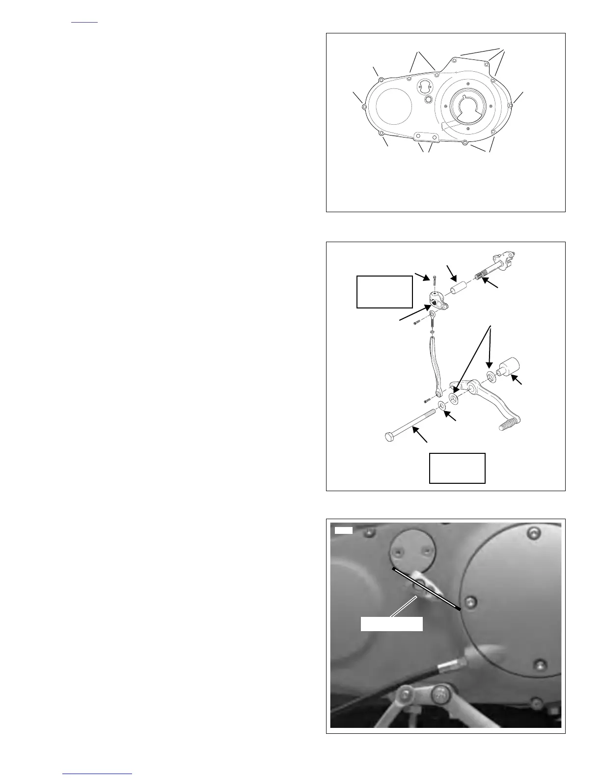
13. See Figure 6-6. Position upper clamp on splined shaft
pointing just below front clutch inspection cover bolt.
(Shift linkage rod in figure is disconnected for clarity.)
14. Apply LOCTITE THREADLOCKER 243 (Blue) to pinch
screw.
15. Install pinch screw to upper clamp and tighten to
59-66
in-lbs
(7-8 Nm).
16. Adjust shift linkage rod length. See 1.6 SHIFT LINKAGE
ROD ADJUSTMENT.
17. Tighten mounting bolt to 27-29 ft-lbs (37-39 Nm).
18. Install muffler. See 2.27 EXHAUST SYSTEM.
19. Install left fairing lower. See 2.38 FAIRING LOWERS.
20. Connect negative cable to battery.
Figure 6-4. Install Primary Cover Bolts
Figure 6-5. Shifter Lever
Figure 6-6. Upper Clamp Position
2
3
2
1
1. 1/4-20 x 1-3/4 in. Bolt with Washers (7)
2. 1/4-20 x 2-1/4 in. Bolt with Washers (4)
3. 5/16-18 x 3-1/2 in. Bolt with Washers (2)
1
x0023a6x
1
2
1
b0922x6x
Washer
Plastic
Bushings (2)
Spacer
Splined
Shaft
Rubber
Mounting Bolt
Washer
27-29 ft-lbs
(37-39 Nm)
Blue Loctite
59-66 in-lbs
(7-8 Nm)
Blue Loctite
Pinch Screw
Upper Clamp