6-22 2002 Buell S3T: Drive/Transmission
HOME
2. Inspect bearings (19, 20) and shifter drum ends. If ends
of shifter drum are pitted or grooved, replace the shifter
drum and bearings. If replacing bearings, see 6.11
ACCESS DOOR BEARINGS.
3. Inspect shifter fork drum (7) for cracks or wear. Replace
if necessary.
ASSEMBLY
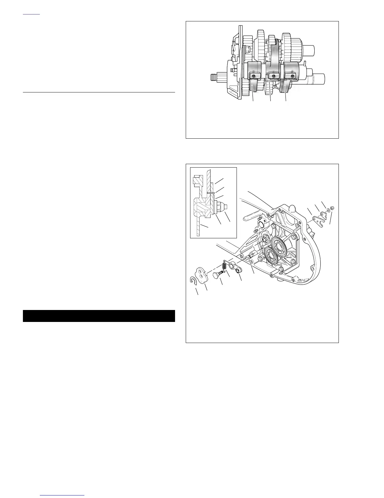
1. See Figure 6-32. Identify all shifter forks before assem-
bly. Note shape of fork and location of fork pin holes.
2. Install shifter forks.
a. Lubricate the shaft bore in of all three shifter forks
(1, 2 and 3) with SPORT-TRANS FLUID.
b. Place 3rd and 5th gear shifter fork (1) in the fork
groove of mainshaft 2nd gear. Be sure the flat side
of fork is facing the access cover.
c. Place 1st and 2nd gear shifter fork (2) in the fork
groove of countershaft 3rd gear. Be sure the flat side
of fork is facing away from the access door.
d. Place 4th gear shifter fork (3) in the fork groove of
mainshaft 1st gear. Be sure the flat side of fork is
facing away from the access door.
3. See Figure 6-31. Install shifter shaft drum.
a. Position the shifter drum shaft so that the neutral
indicator pin (6) is upward. The shaft is then in the
neutral position.
b. Insert the pin end of shifter drum shaft (7) through
the hubs of shifter forks (1, 2 and 3) and through the
bearing in access cover.
c. Align the hole through the top of each shifter fork
with the appropriate cam groove in the shifter drum.
CAUTION
The cotter pins must be inserted through the shifter
forks as shown in Figure 6-32. This will prevent possible
damage to the cotter pins.
4. See Figure 6-31. Secure shifter mechanism.
a. Lubricate the three shifter fork pins (5) with SPORT-
TRANS FLUID.
b. Drop fork pins (5) through the holes in shifter forks.
c. With a small screwdriver press on the pins while
manipulating the forks back and forth until the pin
seats in the drum groove.
d. Secure shifter fork pins with new cotter pins (4).
NOTE
See Figure 6-33. Detent plate (2) and retaining ring (1) are
not installed at this time. These parts are installed during
transmission installation after the final shifter pawl adjustment
is made. See 6.13 TRANSMISSION INSTALLATION AND
SHIFTER PAWL ADJUSTMENT.
5. Install detent plate hardware.
a. At the inside of the access door, place the shifter
drum plate (7) in the groove of the drum shaft. See
inset Figure 6-33.
b. Correctly align reinforcement plate (8) with the pin
pressed in the shifter drum plate (7).
c. Insert detent screw (3) through detent arm (5),
access door, shifter drum plate (7), reinforcing plate
(8) and washer (9).
d. Thread nut (10) on detent screw. Tighten to 13-17 ft-
lbs (18-23 Nm).
NOTE
See Figure 6-28. Install detent arm roller (3) between coun-
tershaft bearing and detent plate.
Figure 6-32. Shifter Fork Identification
Figure 6-33. Detent Plate Mounting
b0348x6x
1. Shifter Fork 3rd and 5th Gear
2. Shifter Fork 1st and 2nd Gear
3. Shifter Fork 4th Gear
2 13
1. Retaining Ring
2. Detent Plate (Typical)
3. Detent Screw
4. Spring
5. Detent Arm
6. Post
7. Shifter Drum Plate
8. Reinforcing Plate
9. Washer
10. Nut
11. Pin
b0154a6x
1
7
b0156x6x
5
10
9
7
11
8
2
3
5
4
9
8
10
6















 To Next Page