7-16 2002 Buell S3T: Electrical
HOME
Ignition Relay
See Figure 7-16 The ignition relay (1) is on the relay block
under the tail section along the right side frame tube. Test the
relay as follows:
1. Test the relay in the same fashion as the starter relay.
See Section 5.
2. Replace the relay with a new relay if necessary.
Starter Relay
See Figure 7-16 The starter relay (2) is on the relay block
under the tail section along the right side frame tube. See 5.3
STARTING SYSTEM DIAGNOSIS.
Ignition Fuse
See Figure 7-16 The ignition fuse is in the fuse block under
the right side of the tail section. Always replace the fuse with
another 20 ampere fuse.
Diodes
1. See Figure 7-16 Remove seat and locate diodes within
relay block.
2. Test diodes using Starter Test flow charts under DIAG-
NOSTICS.
3. Identify the diode which must be replaced. Replace both
diodes if necessary.
4. Replace the diodes by pulling them straight out. The
spare diode may be used in either circuit as long as it is
installed in the correct direction.
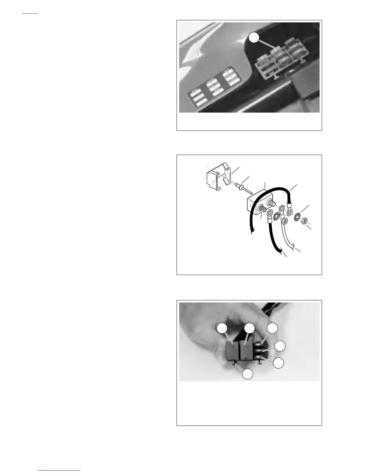
Main Circuit Breaker
See Figure 7-16 Attached to the frame above the battery, the
main circuit breaker (1) is between the ignition key switch and
the battery. Remove the main circuit breaker as follows:
1. Remove seat and fuel tank. See 4.36 FUEL TANK.
2. Remove battery negative cable (3) from frame.
3. See Figure 7-16 Remove nuts (5), star washers (4) and
wire leads (6, 7 and 8) from circuit breaker studs.
4. Remove circuit breaker (3) from circuit breaker clip (1).
5. Install in the reverse order.
Figure 7-14. Fuse Block
Figure 7-15. Circuit Breaker Installation
Figure 7-16. Relay Block
1
1. Ignition Fuse (20A)
1
2
3
4
5
9
7
8
1. Clip
2. Pop Rivet
3. Circuit Breaker
4. Star Washer (2)
5. Nut (2)
6. Wire from Voltage Regulator
7. R Wire from Key Switch
8. BK Wire from Starter
9. Circuit Breaker Gold Post
6
b0401x7x
1. Ignition Relay
2. Starter Relay
3. Starter Circuit Diode
4. Ignition Circuit Diode
5. Spare Diode
6. Mounting Tabs
3
4
6
5
21