2002 Buell S3T: Maintenance 1-17
HOME
1. Install end of a length of plastic tubing over caliper
bleeder valve; place other end in a clean container.
Stand motorcycle upright.
a. Front brake caliper bleeder valve-Figure 1-9.
b. Rear brake caliper bleeder valve-Figure 1-10.
CAUTION
Cover painted surfaces and right handlebar switches and
use care when removing brake reservoir cover and add-
ing D.O.T. 4 brake fluid. Spilling D.O.T. 4 brake fluid on
painted surfaces will result in cosmetic damage. Spilling
brake fluid on switches may render them inoperative.
2. Add D.O.T. 4 BRAKE FLUID to master cylinder reser-
voir. Do not reuse brake fluid.
a. Cover painted surfaces and right handlebar
switches.
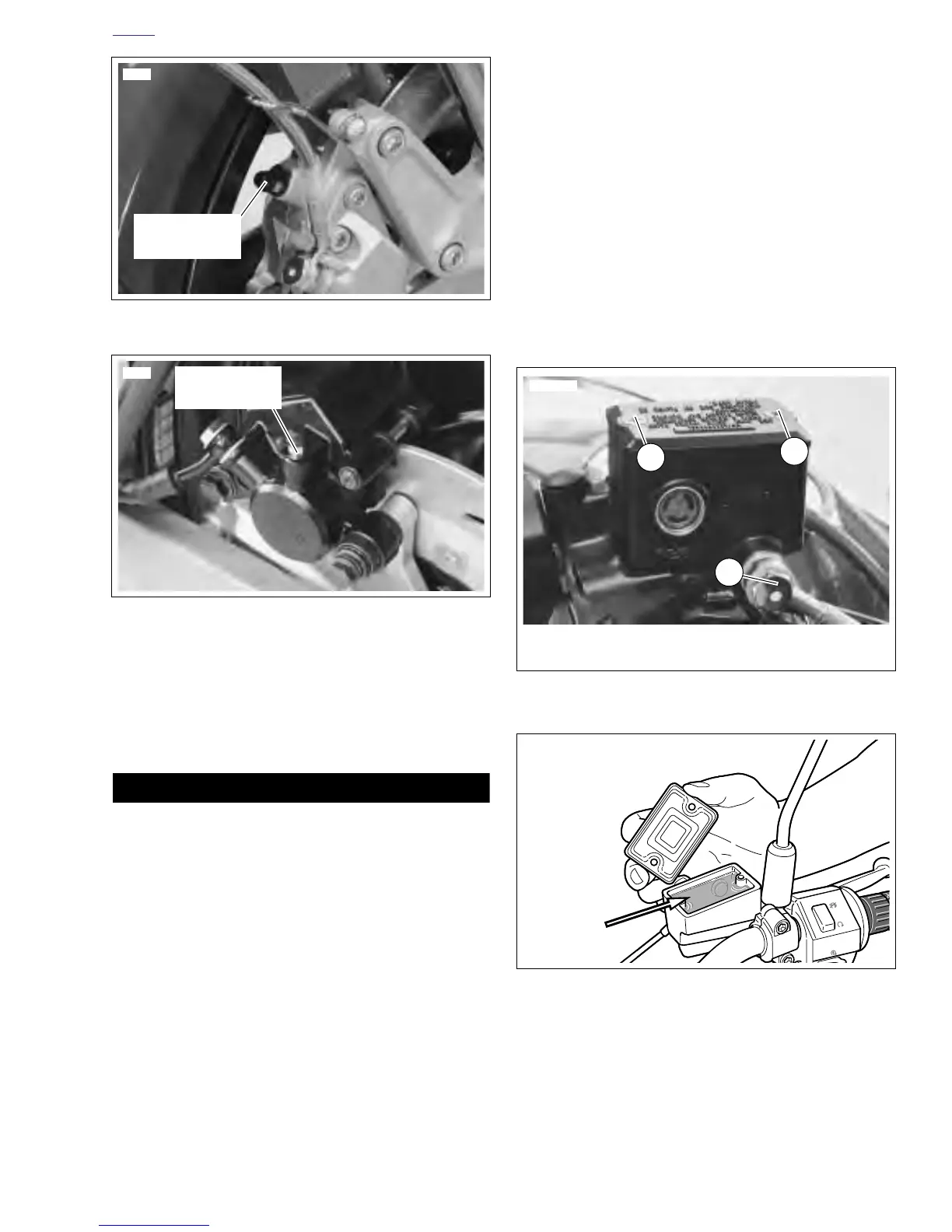
b. Remove two screws from front master cylinder
cover. Bring fluid level to within 1/8 in. (3.2 mm) of
molded boss inside front master cylinder. See Fig-
ure 1-11.
c. Remove cap and gasket from rear master cylinder
reservoir. Bring fluid level to between upper and
lower marks on reservoir. See Figure 1-12.
3. Depress, release and then hold brake lever/pedal to build
up hydraulic pressure.
4. Open bleeder valve about 1/2-turn counterclockwise;
brake fluid will flow from bleeder valve and through tub-
ing. When brake lever/pedal has moved 1/2 to 3/4 of its
full range of travel, close bleeder valve (clockwise). Allow
brake lever/pedal to return slowly to its released position.
5. Repeat Steps 2-4 until all air bubbles are purged.
6. Tighten brake caliper bleeder valves (metric) to 3-5 ft-lbs
(4-7 Nm).
7. Verify master cylinder fluid level as described in Step 2.
8. Attach covers to master cylinder reservoirs.
a. Tighten screws on front master cylinder reservoir to
9-13 in-lbs (1-2 Nm).
b. Tighten cap on rear master cylinder reservoir
securely.
c. Remove cover from painted surfaces and right han-
dlebar switches.
Figure 1-9. Front Brake Caliper Bleeder Valve
Figure 1-10. Rear Brake Caliper Bleeder Valve
6761
Bleeder Valve
(metric)
6746
Bleeder Valve
(metric)
Figure 1-11. Front Master Cylinder
Figure 1-12. Checking Brake Fluid Level
(Switch shown uncovered for clarity)
6735
1
2
1
1. Cover Screws (2) 2. Banjo Bolt (metric)