2002 Buell S3T: Chassis 2-23
HOME
c. Install pad hanger pin (1) (metric). Tighten to 11-
14.5 ft-lbs (15-20 Nm).
d. See Figure 2-25. Install pin plug (4). Tighten to 1.5-
2.1 ft-lbs (2-3 Nm).
11WARNING1WARNING
Use only copper crush banjo washers (See Parts Catalog
for Part No.) with D.O.T. 4 brake fluid. Earlier silver banjo
washers are not compatible with D.O.T. 4 fluid and will
not seal properly over time. Failure to comply may
adversely affect braking ability and lead to brake failure
which could result in death or serious injury.
11WARNING1WARNING
Any leak in brake system will adversely affect brake
operation. To avoid leakage, verify that gaskets, banjo
bolt, hydraulic brake line and caliper bore are completely
clean. Failure to comply could result in death or serious
injury.
4. Connect brake line (1) to caliper using two new banjo
washers (3) and banjo bolt (2) (metric). Tighten to 16-20
ft-lbs (22-27 Nm).
CAUTION
Cover painted surfaces and right handlebar switches and
use care when removing brake reservoir cover and add-
ing D.O.T. 4 brake fluid. Spilling D.O.T. 4 brake fluid on
painted surfaces will result in cosmetic damage. Spilling
brake fluid on switches may render them inoperative.
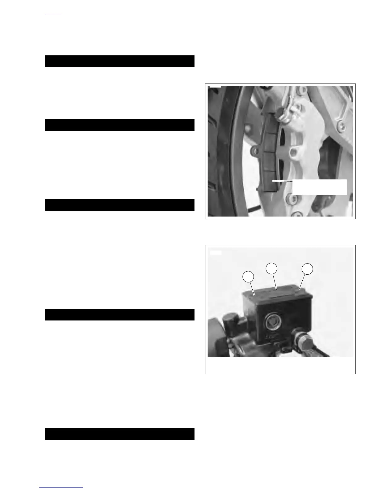
5. See Figure 2-30. Remove both master cylinder cover
screws (2). Remove master cylinder cover (1) and gas-
ket.
6. With the master cylinder in a level position, verify that the
brake fluid level is 1/8 in. (3.2 mm) from molded boss
inside reservoir. Add D.O.T. 4 BRAKE FLUID if neces-
sary.
11WARNING1WARNING
Always verify proper operation of relief port (see Step 7).
A plugged or covered relief port can cause brake drag or
lockup, which may cause loss of vehicle control which
could result in death or serious injury.
7. Verify proper operation of the master cylinder relief port.
Actuate the brake lever with the reservoir cover removed.
A slight spurt of fluid will break the surface if all internal
components are working properly.
8. Install master cylinder cover and cover gasket with two
screws (1). Tighten to 9-13 in-lbs (1-2 Nm).
9. Depress front brake lever several times to set brake pads
to proper operating position within caliper. Bleed brake
system. See 1.5 BRAKES.
11WARNING1WARNING
Check for proper brake lamp operation before riding
motorcycle (see Step 10). Visibility is a major concern for
motorcyclists. Failure to have proper brake lamp opera-
tion could result in death or serious injury.
10. Turn ignition key switch to IGN. Apply brake hand lever to
test brake lamp operation. Turn ignition key switch to
LOCK.
NOTE
Avoid making hard stops for the first 100 miles (160 km) to
allow new brake pads to “wear in” properly with the brake
rotor.
Figure 2-29. Installing Brake Pads
Figure 2-30. Master Cylinder Cover
6545
This surface
against brake rotor
6069a
1. Master Cylinder Cover
2. Screws (2)
2
2
1