2006 Buell Lightning: Chassis 2-71
HOME
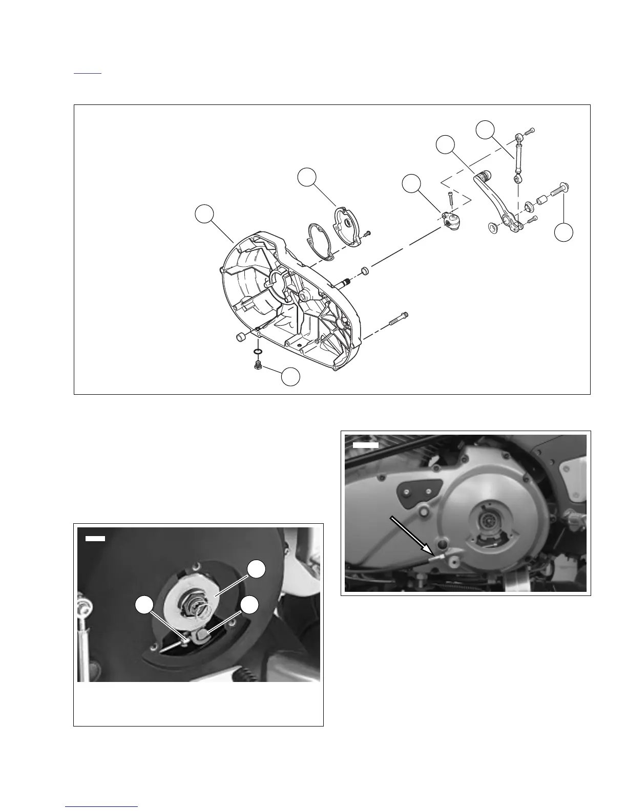
15. Remove complete shift assembly.
a. Remove flange bolt (6) from primary cover.
b. Remove engine shift lever assembly (3). Do not
scratch primary cover.
16. See Figure 2-100. Remove the outer ramp and hook (1)
from the cable end (3) and coupling (2). Remove cable
end from slot in coupling. See 6.3 CLUTCH RELEASE
MECHANISM.
17. See Figure 2-101. Unscrew the cable fitting from the pri-
mary cover. Remove clutch cable and fitting.
18. Remove and discard oring on the clutch cable fitting.
Figure 2-99. Primary Cover and Shifter Assembly
1. Primary cover
2. Clutch inspection cover
3. Engine shift lever
4. Shift pedal assembly
5. Shift linkage assembly
6. Flange head bolt
7. Drain plug
3
1
4
5
6
2
7
b1169x2x
Figure 2-100. Clutch Release Mechanism (Typical)
1. Outer ramp and hook
2. Coupling
3. Cable end
1
23
8413
Figure 2-101. Clutch Cable and Fitting