2006 Buell Lightning: Engine 3-61
HOME
9. See Figure 3-85. Install new gaskets with the bead fac-
ing up. Place lower rocker box assembly (with rocker
arms and shafts) into position. Place push rods in rocker
arm sockets.
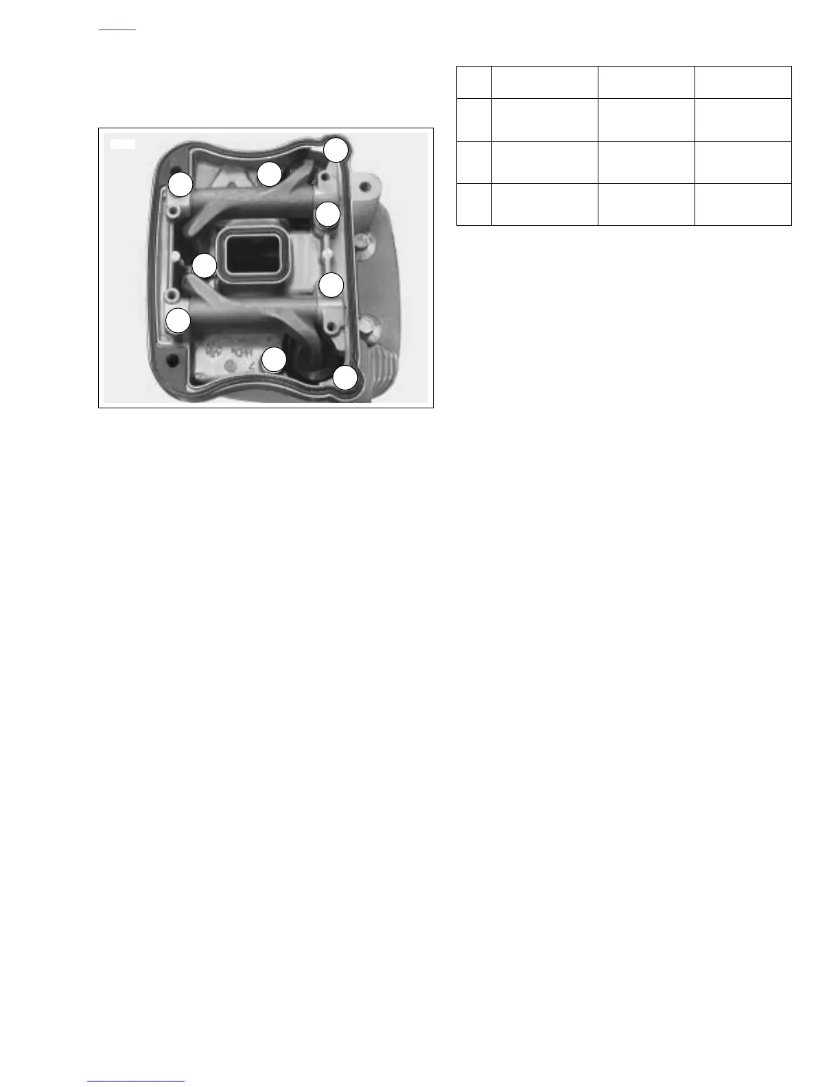
10. See Figure 3-85. Install hardware attaching lower rocker
cover to cylinder head in the following order. After loosely
installing all fasteners, use a cross pattern on the four
large bolts that fasten the lower rocker box to head to
tighten and then torque to specifications. This will bleed
the tappets. Finish tightening remaining fasteners. Fas-
tener sequences, sizes and torque specifications are
listed in Table 3-21.
a. Tighten bolts (1) to 18-22 ft-lbs (24-30 Nm).
b. Tighten bolts (2) to 135-155 in-lbs (15-18 Nm).
c. Tighten screws (3) to 135-155 in-lbs (15-18 Nm).
11. See Figure 3-84. Install upper rocker covers.
a. Place a new inner gaskets on lower rocker box
assemblies.
b. Place a new lower gaskets on lower rocker cover.
c. Install upper rocker cover using screws with washers
and new fiber seals. Tighten screws to 120-156 in-
lbs (13.6-17.6 Nm).
Figure 3-85. Lower Rocker Box Fasteners
4688a
3
3
2
2
2
1
1
1
1
4688a
Table 3-21. Lower Rocker Box Fasteners
No. ITEM SIZE TORQUE
1 Bolt w/washer
5/16-18 X 2-1/2
18-22 ft-lbs
(24-30 Nm)
2 Bolt w/washer
1/4-20 X 1-1/4
135-155 in-lbs
(15.2-17.5 Nm)
3 Screw w/washer
1/4-20 X 1-1/2
135-155 in-lbs
(15-18 Nm)