6-24 2006 Buell Lightning: Drive/Transmission
HOME
IDLER PULLEY REMOVAL
1. See Figure 6-43. Loosen rear axle pinch fastener (2).
2. Unthread axle approximately 15 rotations to release ten-
sion from drive belt.
3. Remove chin fairing fasteners. See 2.36 CHIN FAIRING.
4. Remove front sprocket cover. See 2.33 SPROCKET
COVER.
5. See Figure 6-44. Remove idler pulley bracket nuts and
washers (5) from studs (3).
6. Slide idler pulley bracket (4) off studs (3).
7. See Figure 6-44. Inspect pulley by spinning wheel (1)
and checking for wheel bearing wear. See INSPECTION
under 1.9 DRIVE BELT.
8. If pulley wheel needs replacement, remove fastener (6),
washer and nut (2) from idler pulley bracket (4) and dis-
card wheel. Replace with new pulley wheel (1).
NOTE
The pulley wheel bearings can not be replaced separately.
IDLER PULLEY INSTALLATION
1. See Figure 6-44. Install new or existing pulley wheel (1),
if removed, and tighten washer and nut (2) wheel fas-
tener (6) to 20-23 ft-lbs (27.1-31.2 Nm).
2. Slide idler pulley bracket (4), washer and nuts (5) on to
studs (3) and tighten to 33-35 ft-lbs (45-47 Nm). See
DRIVE BELT INSTALLATION.
3. Install front sprocket cover. See 2.33 SPROCKET
COVER.
4. Install chin fairing fasteners and tighten to 36-48 in-lbs
(4-5 Nm). See 2.36 CHIN FAIRING.
NOTE
Never tighten rear axle with swingarm brace removed.
5. See Figure 6-43. Install and tighten rear axle (1) to23-
27 ft-lbs (31.2-36.6 Nm), back off two full turns and then
retighten to 48-52 ft-lbs (65.1-70.5 Nm). See 6.6 DRIVE
BELT SYSTEM.
6. Tighten rear axle pinch fastener (2) to 40-45 ft-lbs (54-
61 Nm).
Figure 6-43. Rear Wheel Mounting, Right Side
8420
2
1. Axle
2. Pinch bolt fastener
1
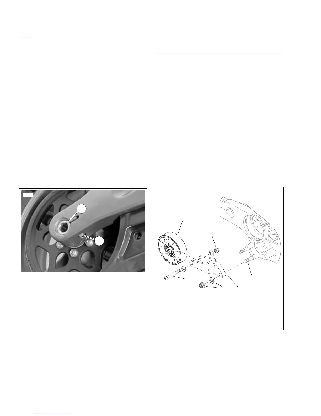
Figure 6-44. Idler Pulley Assembly
b1106x6x
1
4
2
3
6
1. Wheel
2. Wheel nut
3. Stud
4. Idler pulley bracket
5. Idler pulley bracket nut and washer
6. Wheel fastener
5