2006 Buell Lightning: Electrical 7-43
HOME
HEADLIGHT BULBS
Removal
1. Remove seat. See 2.43 SEAT.
NOTE
On XB9SX models it will be necessary to remove headlight
grille and reinstall once defective bulbs have been replaced.
1WARNING1WARNING
To prevent accidental vehicle start-up, which could
cause death or serious injury, disconnect negative (-)
battery cable before proceeding. (00048a).
2. Disconnect negative battery cable.
1CAUTION
Handle bulb carefully and wear eye protection. Bulb con-
tains Halogen gas under pressure, which, if not handled
carefully, could cause serious eye injury. (00062a)
CAUTION
Never touch the quartz bulb. Fingerprints will etch the
glass and decrease bulb life. Grab the bulb with paper or
a clean, dry cloth. Failure to do so could result in bulb
damage. (00210a)
3. See Figure 7-51. Remove rubber boot from headlight
housing.
4. Unplug headlight bulb connectors (3) and/or (4).
5. Release bulb holder (2) from headlight housing clips.
6. Pull bulb housing from headlight housing.
Installation
NOTE
Not using the specified bulb may cause charging system prob-
lems.
1CAUTION
Handle bulb carefully and wear eye protection. Bulb con-
tains Halogen gas under pressure, which, if not handled
carefully, could cause serious eye injury. (00062a)
CAUTION
Never touch the quartz bulb. Fingerprints will etch the
glass and decrease bulb life. Grab the bulb with paper or
a clean, dry cloth. Failure to do so could result in bulb
damage. (00210a)
1. See Figure 7-51. Align tabs on bulb (5) with tabs on
headlight (1). Insert bulb.
2. Close the bulb holder (2).
3. Connect the headlight bulb connector.
NOTE
If the rubber boots are not installed correctly the wiring har-
nesses can contact the edge of the forward frame mount. The
wiring harness guides must be installed at a 20 degree angle.
4. See Figure 7-53. Install rubber boot.
a. When installing the rubber boots on the back of the
headlight housing be sure to align the harness
guides or spigots with the casting marks on the
headlight housing.
b. When the spigots are aligned with the casting marks
the wiring harness will be at approximately 20
degrees.
5. Connect negative battery cable.
Be sure that all lights and switches operate properly
before operating motorcycle. Low visibility of rider can
result in death or serious injury. (00316a)
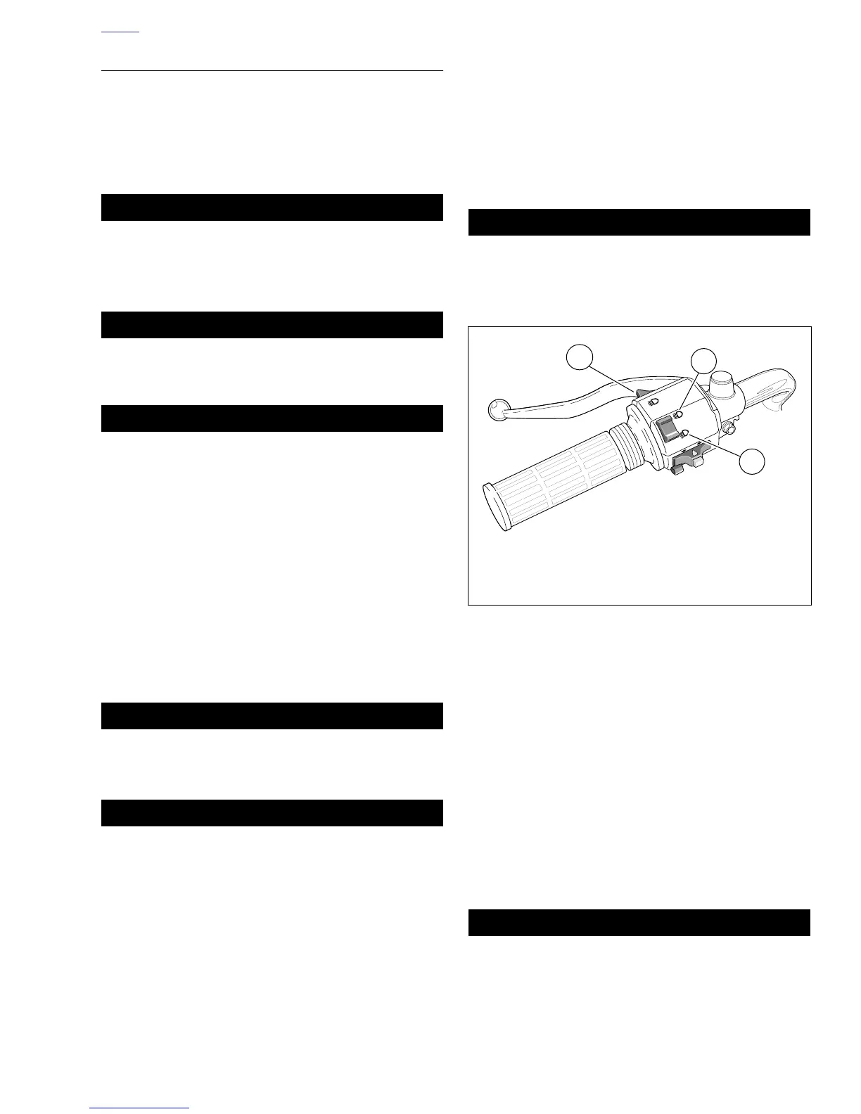
6. See Figure 7-52. Check headlight for proper operation. If
operation fails, reread procedure and verify that all steps
were performed.
a. Turn ignition key switch to ON.
b. Check headlight LOW (3) and HIGH beam (2) set-
tings.
c. Set headlight to LOW beam. Press passing lamp
switch (1). Headlight should flash HIGH beam for as
long as the switch is pressed.
d. Turn ignition key switch to OFF.
7. Align headlight. See 1.18 HEADLIGHTS.
After installing seat, pull upward on front of seat to be
sure it is in locked position. While riding, a loose seat can
shift causing loss of control, which could result in death
or serious injury. (00070a)
8. Install seat. See 2.43 SEAT.
Figure 7-52. Headlight Controls
1. Passing lamp switch
2. HIGH beam
3. LOW beam (always on when bike is running)
b0586x0x
1
3
2