7-52 2006 Buell Lightning: Electrical
HOME
INSTALLATION
Right Side
1. Attach throttle cables to hand control. See 2.23 THROT-
TLE CONTROL.
2. Install right switch housing.
a. Position housing on right handlebar by engaging
alignment pin on front housing with hole in handle-
bar.
b. Attach switch housing with two mounting fasteners
and tighten to 25-33 in-lbs (3-4 Nm).
3. Attach brake switch connector [121].
4. Attach right handlebar switch connector [22] to wire har-
ness. See D.1 HOSE AND WIRE ROUTING for wire rout-
ing information.
1WARNING1WARNING
Be sure that all lights and switches operate properly
before operating motorcycle. Low visibility of rider can
result in death or serious injury. (00316a)
5. Check handlebar switch for proper operation. If operation
fails, reread procedure and verify that all steps were per-
formed.
a. Turn ignition key switch to ON.
b. Set ENGINE STOP SWITCH to RUN.
c. Start motorcycle.
d. Turn ignition key switch to OFF.
6. Turn ignition key switch to OFF.
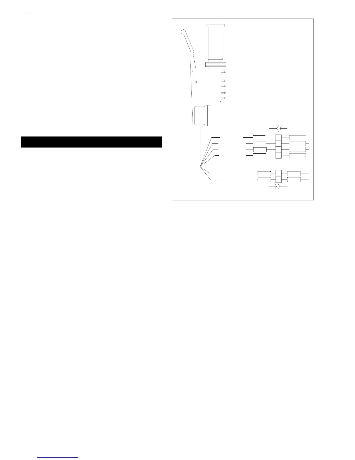
Figure 7-67. Right Handlebar Switch Connection
1
2
1
3
2
4
Right Handlebar Switch
Brake Switch
To starter relay
GY
Accessory power
GY/O
W/BK
W/BK
W/BK
W/BK
BK/R
BK/R
O
O
R/Y
R/Y
To stoplight
From Ign. relay
To Ign. relay
From Ign. relay
[121A] [121B]
[22A] [22B]