2006 Buell Lightning: Electrical 7-53
HOME
Left Side
1. Install left switch housing.
a. Position housing on left handlebar by engaging
alignment pin on front housing with hole in handle-
bar.
b. Attach switch housing with three mounting fasteners
and tighten to 25-33 in-lbs (3-4 Nm).
2. Connect clutch switch [95].
3. Attach right handlebar switch connector [24] to wire har-
ness. See D.1 HOSE AND WIRE ROUTING for wire rout-
ing information.
1WARNING1WARNING
Be sure that all lights and switches operate properly
before operating motorcycle. Low visibility of rider can
result in death or serious injury. (00316a)
4. Check handlebar switch for proper operation. If operation
fails, reread procedure and verify that all steps were per-
formed.
a. Turn ignition key switch to ON.
b. Check headlight LOW and HIGH beam settings.
c. Set headlight to LOW beam. Press passing lamp
switch. Headlight should flash HIGH beam for as
long as the switch is pressed.
d. Check left and right turn signals.
e. Activate horn by pressing horn switch.
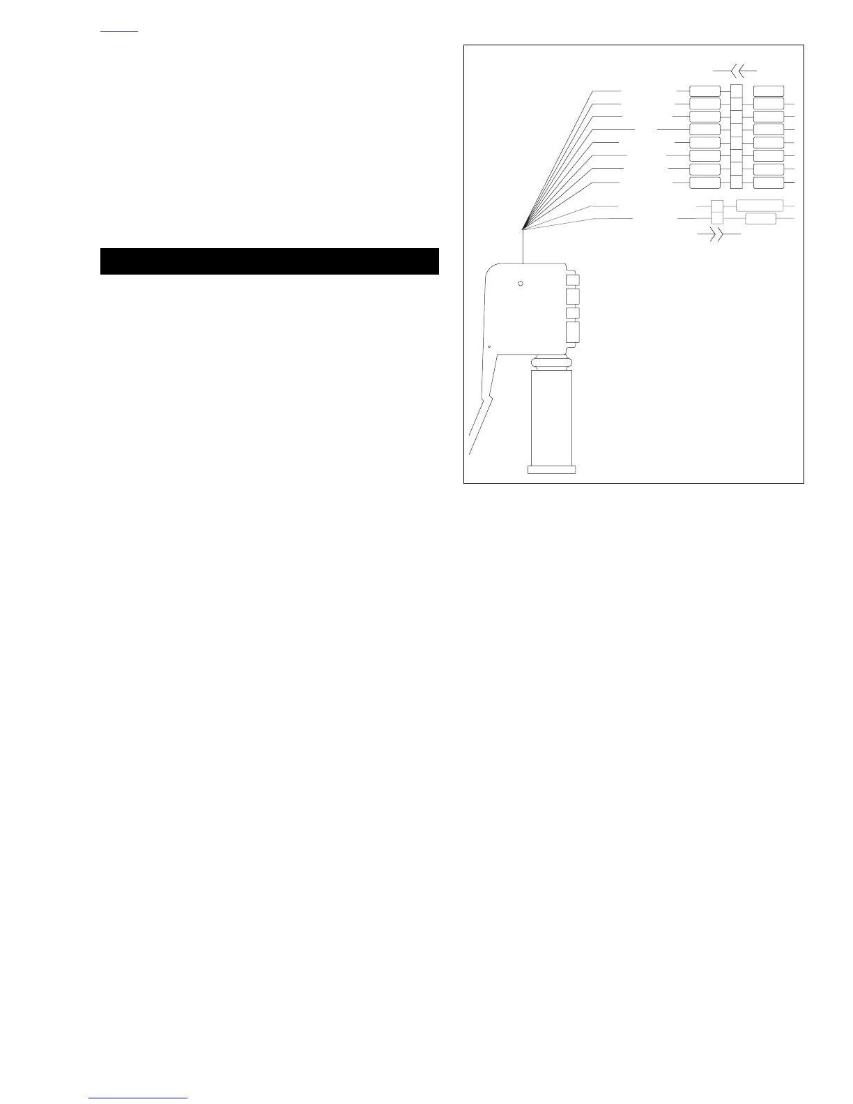
Figure 7-68. Left Handlebar Switch Connection
b1103x7x
Clutch Switch
Left Handlebar Switch
Y/BK
To headlamp
BE/W
Y/BK
V/BN
Light power
High beam
Horn
From flasher
Left turn
Right turn
Horn power
To interlock circuit
To ground
Y
W
W
Y
V
O
V
O
BN
BN
BE BE
BK
TN/LTGN
[24B][24A]
[95A][95B]