131I-Modell - 11/12 - Ausgabe 09/11 - 2096165 - BUE-0056-05EN
Electrical system
8
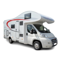
The fuel cell consists of several components that are installed in the rear
storage space (Fig. 132) and of an operating unit (Fig. 134) in the living area.
The following components are on the fuel cell (Fig. 132,6):
z The connector for the air discharge hose (Fig. 132,4) or the filling hole for
the service fluid
z the off-heat tube (Fig. 132,5)
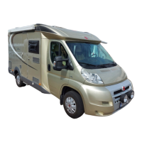
z electrical connections (Fig. 132,3) with data interface (Fig. 133,2), device
connection (Fig. 133,3) and connection for the operating panel (Fig. 133,1)
A tank cartridge belongs to the fuel cell (Fig. 132,6). It is connected to the fuel
cell via a tank connection (Fig. 132,2).
The tank cartridge is firmly fixed in the tank cartridge holder (Fig. 132,1).
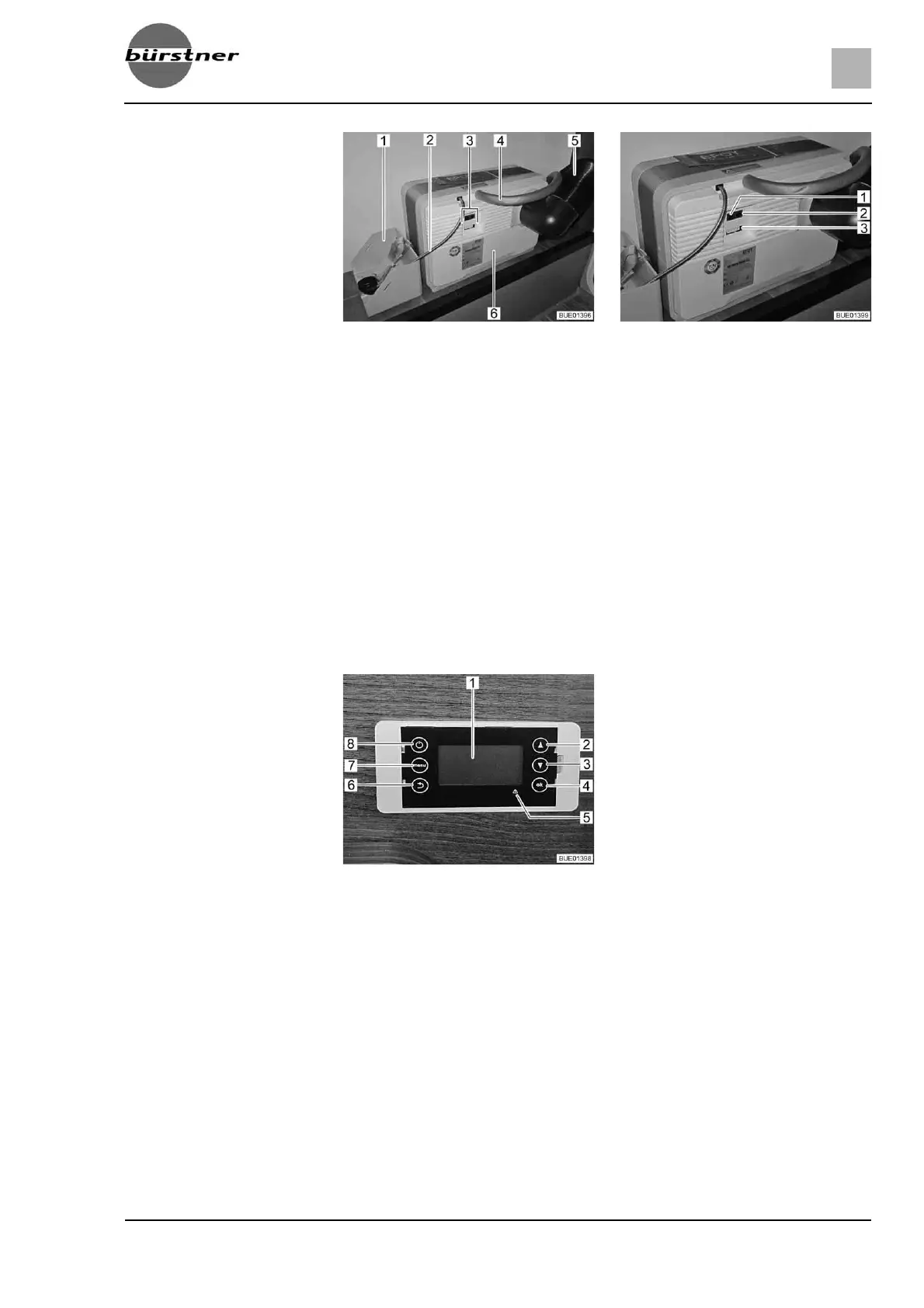
The fuel cell automatically charges the living area batteries if their voltage falls
below 12,3 V and if the fuel cell is switched on using the On/Off key
(Fig. 134,8).
Operating unit The display (Fig. 134,1) of the operating unit has four lines.
The first line displays the selected operating mode:
z Automatic
z On
z Off
The second line displays the current operating status:
z Standby
z Charging mode
z Shutdown procedure
z Battery protection
z Antifreeze
The other two rows show information such as battery voltage, charging current
and filling level of the tank cartridge.
Fig. 132 Fuel cell with tank cartridge Fig. 133 Connector panel of the fuel cell
Fig. 134 Operating unit fuel cell
1 Display
2 Scroll upwards through menu
3 Scroll downwards through menu
4 Confirmation/OK
5 Fault display (red LED)
6Back
7Menu
8On/Off
 Loading...