52 I-Modell - 11/12 - Ausgabe 09/11 - 2096165 - BUE-0056-05EN
Pitching the motorhome
5
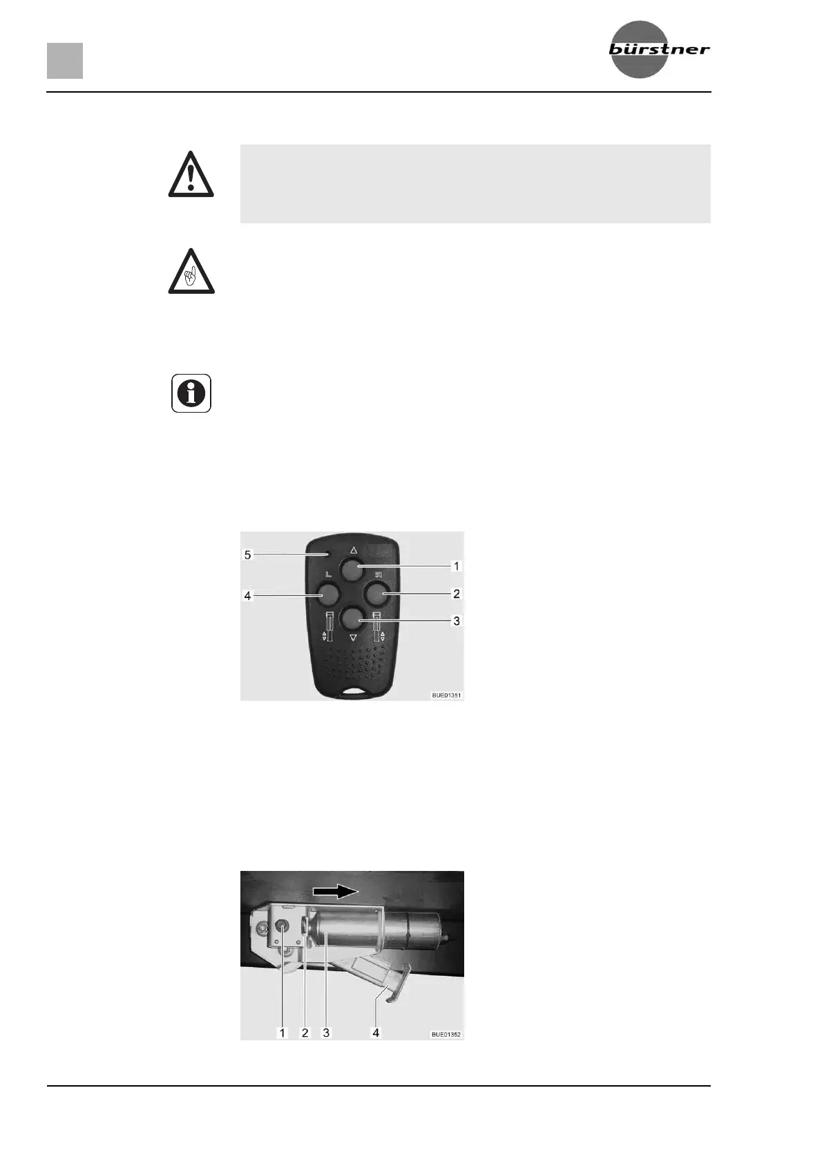
5.5.4 Electrical steady legs (AL-KO) (special equipment)
Button functions z Preselection: steady leg left (Fig. 36,4)
z Preselection: steady leg right (Fig. 36,2)
z Retract steady leg (Fig. 36,1)
z Extend steady leg (Fig. 36,3)
z Control LED (Fig. 36,5)
Each time a button is pressed, the control LED (Fig. 36,5) flashes.
X Always observe the electrical steady legs when extending or retracting
them.
X When extending or retracting the steady legs, ensure that no one is in
the vehicle. Risk of injury due to unexpected rolling motion.
Z Never extend the steady legs so far that the tyres of the vehicle are not in
contact with the ground. This could damage the body and chassis and the
brakes will not work.
Z The steady legs are designed only to support the vehicle, not to level it.
Z Steady legs need sufficient ground clearance to be able to fold out verti-
cally.
Z The electrical steady legs can only be operated with the ignition switched
off.
Z If the remote control is not operated for two minutes after the controller has
been activated, the controller automatically switches off.
Z When a key on the remote control is pressed, the indicator lamp flashes.
Z If the steady legs are extended and the ignition is switched on, a pulsating
warning tone is heard. The warning tone stops after the ignition has been
switched off.
Fig. 36 Remote control for electrical
steady legs
Fig. 37 Electrical steady leg on vehicle