Appendix B Electrical Drawings Page B-15
Buskro Ltd. BK730-2 Tabber
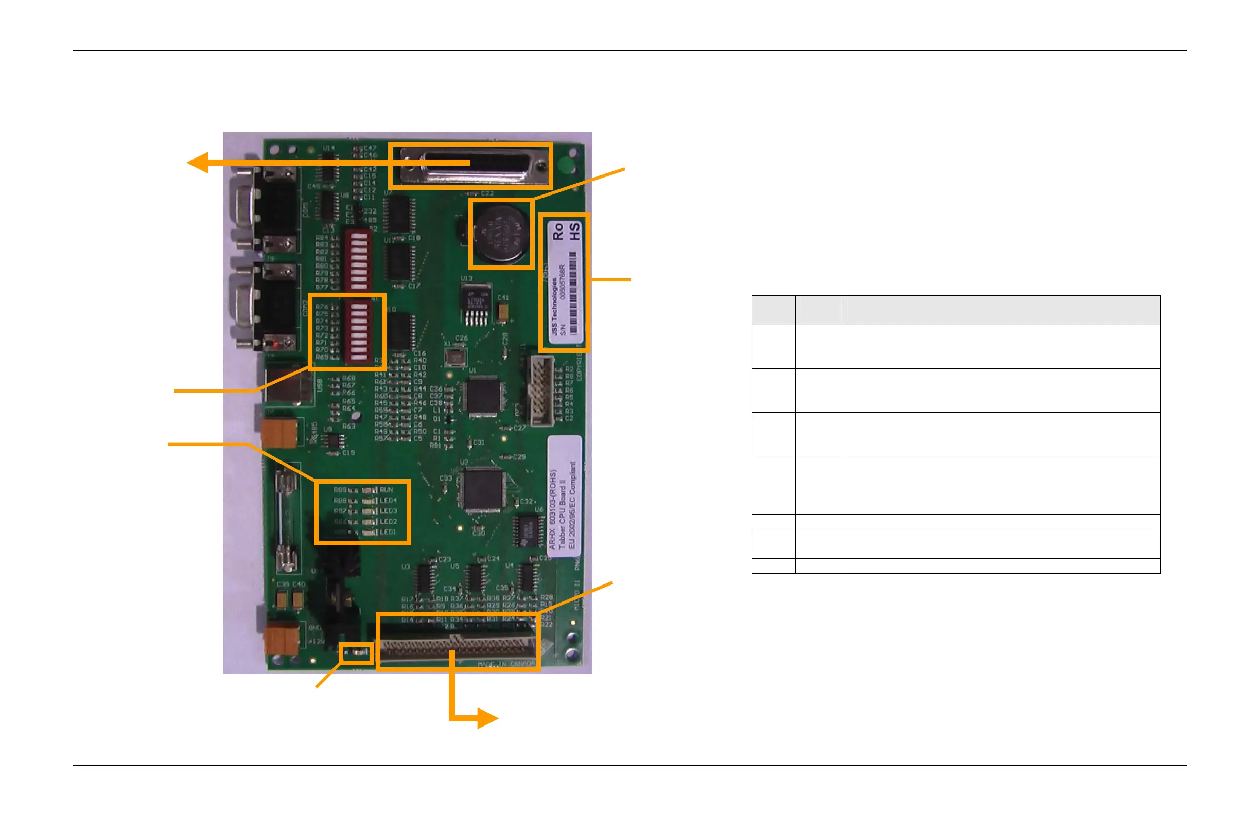
Figure B-15:
Tabber CPU Board II DIP Switch Settings and Programming
The Tabber II CPU Board (p/n 9101275) is a printed circuit board
that is used to control the Buskro Tabbing Head. Version 2.0 of the
Tabber II software is the initial release.
Version 2.0 of the SSB II software is designed to be functionally
equivalent to the Tabber CPU board V1.7 software. The Tabber II
oard is a surface mount board that has been designed to be capable
of RoHS production.
The Tabber II board RUN LED will blink (1 second on – 1 second
off) to indicate normal operation.
Connector J2
DIP Switch 1
3VDC Battery,
CR2032
LED Indicators
RUN = For normal operation
LED4 = Not Used
LED3 = Not Used
LED2 = Not Used
LED1 = Not Used
RoHS S/N Label
Connects to Tabber Interface Board (p/n 9101133) via System
Support Interface Cable (p/n 606311A)
Connects to
9101134C10 (cable
#10) of Tabber
Connector Plate
Harness (p/n
9101134A
PWR LED
Will be on when 12 VDC is
a
lie
Table A – Tabber II CPU Board Dip Switch Assignments
DIP # Default
Setting
Function
1
On
Off
For normally de-energized stop relay
For normally energized stop relay
2
On
Off
For 660 DPI (7IB) base
For 600 DPI Tabber base
3
On
Off
For 5-phase tab stepper motor
For 2-phase tab stepper motor
4
On
Off
For Lateral Visions 2-phase tab stepper motor driver
For Oriental Motor 2-phase tab stepper motor driver
5 Off Reserved
6 Off Reserved
7 Off Turn ON to perform a factory reset (all other DIP switches
must be off).
8 Off Turn ON to enter the firmware update mode
To reprogram the board:
1. Turn off power to the head.
2. Switch DIP 7 ON and all other DIP switches OFF.
3. Turn the head power on and wait until the board reprograms (approximately 30 sec).
4. Turn the head power off.
5. Return the DIP switch settings to the desired configuration for normal operation.
The board is now programmed and ready for use.