Operation 215
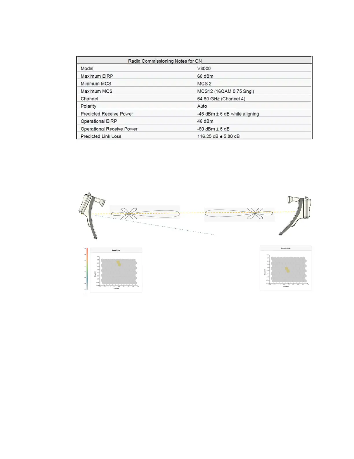
Figure 234:
An example of the receive level when aligning - Link planner
5. Make use of the direction of arrival information (if there is any elevation or azimuth mismatch) to
physically align the radio antennas.
l When there is an elevation mismatch (as shown in Figure 235):
Figure 235:
Example of the elevation mismatch
In Figure 235, the angles are exaggerated to show the point. In this example, consider that
the radio has been misaligned by a down-tilt of 2 degrees behind the unit (from an
installer’s view side). This means that the angle of the beam selected might be in the +2
degrees direction in the elevation due to beamforming. The aim is to get the optimal
boresight beam. Therefore, the radio must be up tilted in the elevation direction by 2
degrees. The selected beam is now closer to the boresight beam, as shown in Figure 236.





 To Next Page