System Planning 91
CNs and DNs get prefixes from the respective PoP zone which is allocated by the controller. CNs and DNs
see multiple PoP nodes in the mesh, they select PoP to form GRE tunnel, by matching their lo IPv6
address with PoPs lo IPv6 address. The longest prefix match is selected as the best PoP for L2 GRE
Tunnel establishment. The multi-PoP setup gives the advantage that user data traffic can take alternate
routes if the best route is unavailable for some reason. Open/R makes this selection to route the traffic. If
PoP is unavailable, CNs and DNs switch to the next best PoP. They however keep track of their primary
PoP availability and switch to it once it becomes online.
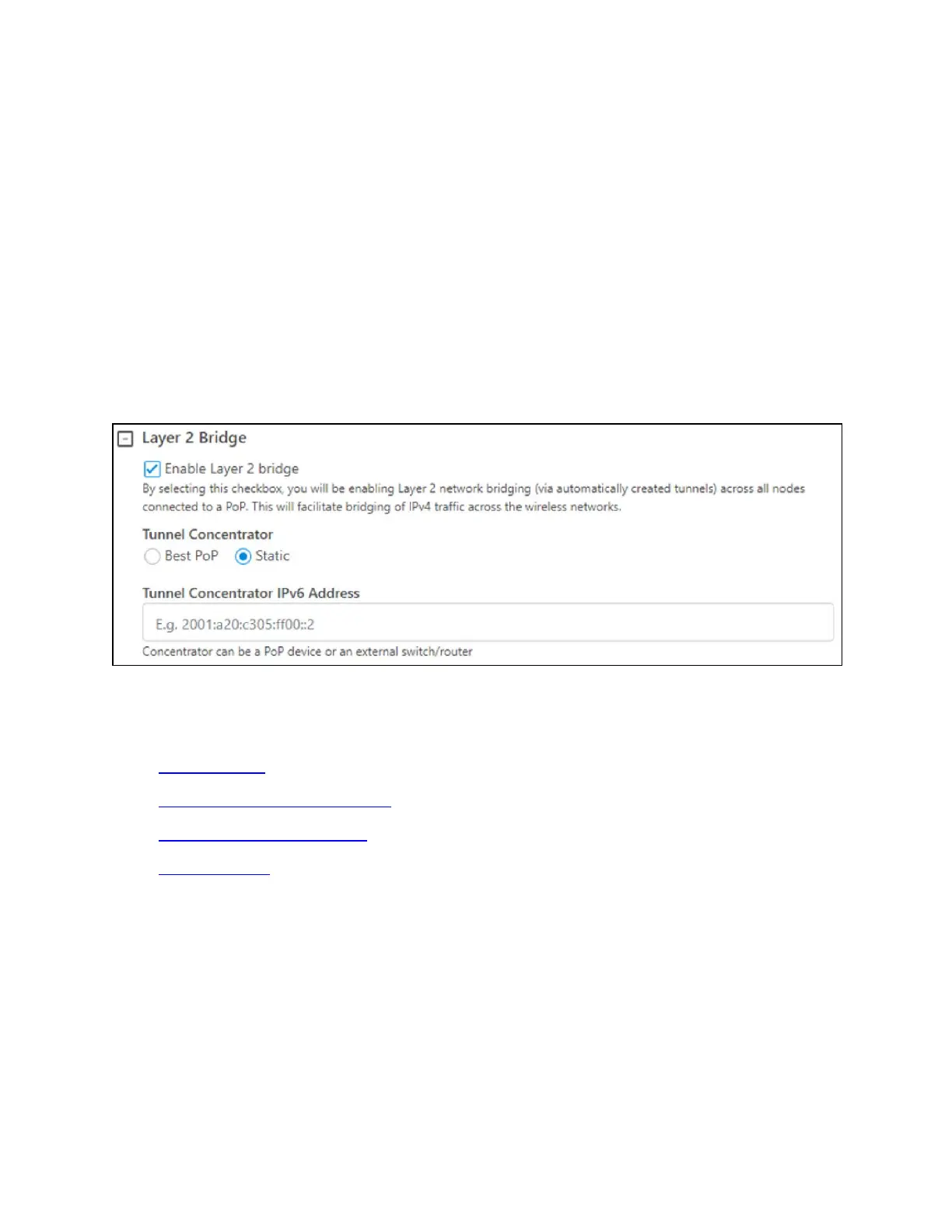
External Layer 2 Concentrator support
The external device can be used as an L2 GRE Concentrator. Concentrator could be a Linux server or any
router or switch supporting IPv6 L2 GRE tunnels. Example: Juniper MX 100.
Select the Static tunnel concentrator option and provide an IPv6 address to configure the external
concentrator IPv6 address.
Figure 64:
Layer 2 Tunnel Concentrator
Multi-PoP deployments
You must take care of the following aspects in the multi-PoP deployments:
l Layer 2 domain
l Open/R on the PoP interface port
l MTU of upstream switch ports
l Prefix allocation
Layer 2 domain
All cnWave PoP nodes must be connected to the same Layer 2 broadcast domain. PoP nodes learn about
other PoP nodes using IPv6 multicast packets, which do not cross broadcast domain.
This allows cnWave PoP nodes to forward traffic to other cnWave PoP nodes via a wired connection
when the routing path of the other PoP node is closer to the traffic’s destination. This concept is called
Tromboning, as the traffic enters one PoP node and then leaves to another PoP node.